
 https://cdn.comparitech.com/wp-content/uploads/2021/02/How-to-Set-Up-a-VLAN-final-design-300x170.jpg 300w" alt="How to Set Up a VLAN final design" width="628" height="355" style="box-sizing: border-box; border: 0px; vertical-align: middle; font-weight: inherit; outline: 0px; contain-intrinsic-size: 3000px 1500px; margin: 0px auto; display: block; max-width: 100%; height: auto; border-radius: 6px;" loading="lazy" decoding="async" />
 https://cdn.comparitech.com/wp-content/uploads/2021/02/Connecting-switch-and-computers-1-300x170.jpg 300w" alt="Connecting switch and computers 1" width="628" height="355" style="box-sizing: border-box; border: 0px; vertical-align: middle; font-weight: inherit; outline: 0px; contain-intrinsic-size: 3000px 1500px; margin: 0px auto; display: block; max-width: 100%; height: auto; border-radius: 6px;" loading="lazy" decoding="async" />
 https://cdn.comparitech.com/wp-content/uploads/2021/02/Connecting-switch-and-computers-2-300x170.jpg 300w" alt="Connecting switch and computers 2" width="628" height="355" style="box-sizing: border-box; border: 0px; vertical-align: middle; font-weight: inherit; outline: 0px; contain-intrinsic-size: 3000px 1500px; margin: 0px auto; display: block; max-width: 100%; height: auto; border-radius: 6px;" loading="lazy" decoding="async" />
 https://cdn.comparitech.com/wp-content/uploads/2021/02/ACCT-and-LOGS-VLAN-300x170.jpg 300w" alt="ACCT and LOGS VLAN" width="628" height="355" style="box-sizing: border-box; border: 0px; vertical-align: middle; font-weight: inherit; outline: 0px; contain-intrinsic-size: 3000px 1500px; margin: 0px auto; display: block; max-width: 100%; height: auto; border-radius: 6px;" loading="lazy" decoding="async" />
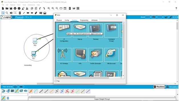 https://cdn.comparitech.com/wp-content/uploads/2021/02/Desktop-configuration-and-IP-configuration-menu-300x170.jpg 300w" alt="Desktop configuration and IP configuration menu" width="628" height="355" style="box-sizing: border-box; border: 0px; vertical-align: middle; font-weight: inherit; outline: 0px; contain-intrinsic-size: 3000px 1500px; margin: 0px auto; display: block; max-width: 100%; height: auto; border-radius: 6px;" loading="lazy" decoding="async" />
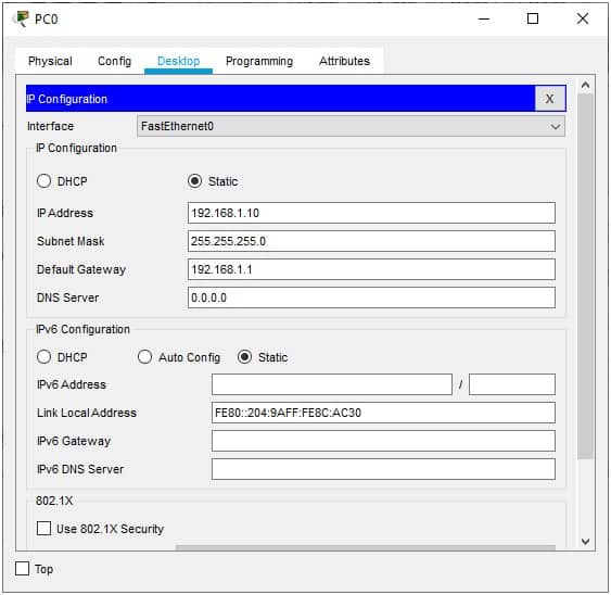 https://cdn.comparitech.com/wp-content/uploads/2021/02/IP-address-and-Default-Gateway-configuation-300x292.jpg 300w" alt="IP address and Default Gateway configuration" width="563" height="548" style="box-sizing: border-box; border: 0px; vertical-align: middle; font-weight: inherit; outline: 0px; contain-intrinsic-size: 3000px 1500px; margin: 0px auto; display: block; max-width: 100%; height: auto; border-radius: 6px;" loading="lazy" decoding="async" />
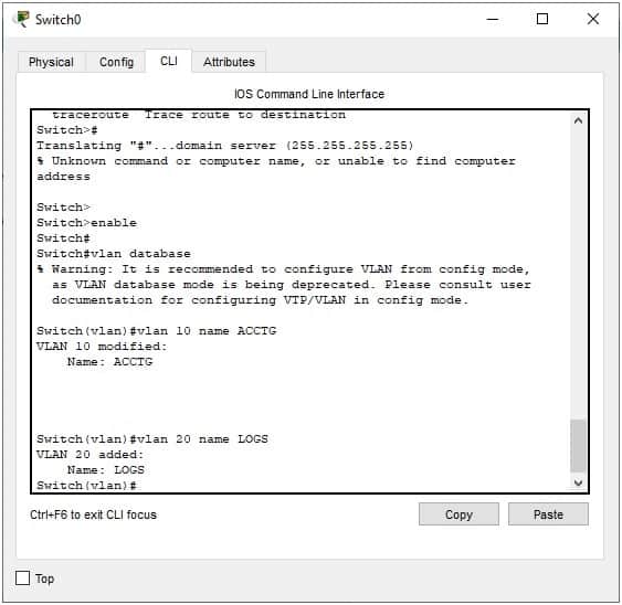 https://cdn.comparitech.com/wp-content/uploads/2021/02/Switch-create-VLAN-CLI-300x292.jpg 300w" alt="Switch create VLAN CLI" width="563" height="548" style="box-sizing: border-box; border: 0px; vertical-align: middle; font-weight: inherit; outline: 0px; contain-intrinsic-size: 3000px 1500px; margin: 0px auto; display: block; max-width: 100%; height: auto; border-radius: 6px;" loading="lazy" decoding="async" />
 https://cdn.comparitech.com/wp-content/uploads/2021/02/Switch-create-VLAN-GUI-300x292.jpg 300w" alt="Switch create VLAN GUI" width="563" height="548" style="box-sizing: border-box; border: 0px; vertical-align: middle; font-weight: inherit; outline: 0px; contain-intrinsic-size: 3000px 1500px; margin: 0px auto; display: block; max-width: 100%; height: auto; border-radius: 6px;" loading="lazy" decoding="async" />
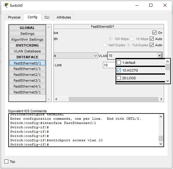 https://cdn.comparitech.com/wp-content/uploads/2021/02/Assign-switch-port-to-a-VLAN-300x292.jpg 300w" alt="Assign switch port to a VLAN" width="563" height="548" style="box-sizing: border-box; border: 0px; vertical-align: middle; font-weight: inherit; outline: 0px; contain-intrinsic-size: 3000px 1500px; margin: 0px auto; display: block; max-width: 100%; height: auto; border-radius: 6px;" loading="lazy" decoding="async" />
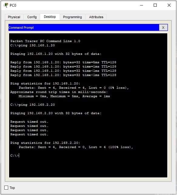 https://cdn.comparitech.com/wp-content/uploads/2021/02/VLAN-ping-test-no-router-272x300.jpg 272w" alt="VLAN ping test - no router" width="584" height="644" style="box-sizing: border-box; border: 0px; vertical-align: middle; font-weight: inherit; outline: 0px; contain-intrinsic-size: 3000px 1500px; margin: 0px auto; display: block; max-width: 100%; height: auto; border-radius: 6px;" loading="lazy" decoding="async" />
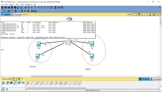 https://cdn.comparitech.com/wp-content/uploads/2021/02/Router-sub-interface-configuration-shortcut-menu-300x170.jpg 300w" alt="Router sub-interface configuration shortcut menu" width="628" height="355" style="box-sizing: border-box; border: 0px; vertical-align: middle; font-weight: inherit; outline: 0px; contain-intrinsic-size: 3000px 1500px; margin: 0px auto; display: block; max-width: 100%; height: auto; border-radius: 6px;" loading="lazy" decoding="async" />
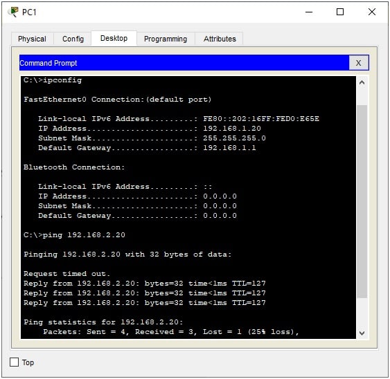 https://cdn.comparitech.com/wp-content/uploads/2021/02/Ping-LOGS-PC-from-ACCT-PC-Success-300x292.jpg 300w" alt="Ping LOGS PC from ACCT PC - Success" width="563" height="548" style="box-sizing: border-box; border: 0px; vertical-align: middle; font-weight: inherit; outline: 0px; contain-intrinsic-size: 3000px 1500px; margin: 0px auto; display: block; max-width: 100%; height: auto; border-radius: 6px;" loading="lazy" decoding="async" />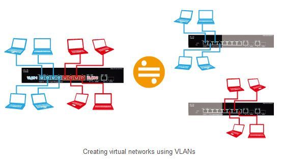
Intro
VLANs are one of the most complicated concepts to wrap your head around when you're getting started
with computer networking. Heck, I mean, they're even confusing for experienced network admins.
So in this video, I'm gonna try to break down the complex concept of VLANs to make them easier
to understand and therefore easier to use. So if VLANs are a concept that you've been struggling with,
pay careful attention to this video and hopefully by the end, you'll have a much greater understanding
of exactly how VLANs work. Okay, we've got a lot to cover, so let's get started.
VLANs can be difficult to understand.
So if you need any help configuring VLANs in your own network, the friendly and knowledgeable technicians
at Rogue Support are here to assist. Whether you wanna set up an isolated guest network or a secure subnet for all of your IoT devices,
Rogue Support technicians are well versed in VLAN setup and troubleshooting. It's as simple as opening up a ticket,
receiving bids on your job, and then working with the technician that you select on your schedule.
And you don't pay anything until your issue is resolved. We're also proud to announce the Rogue Support Referral Program
that allows you to make some extra cash by referring customers to Rogue Support for all of their computer networking,
security, and wireless needs. If you're interested in becoming a Rogue Support Referral partner,
be sure to visit rogue.support.referrals for more info. VLAN stands for Virtual Local Area Network.
LAN Basics
So let's start with the LAN portion of VLAN to get this video started. A LAN, or local area network,
in its simplest form is the inside interface of a router. So if you go down to Best Buy
and you purchase a router off the shelf, you're gonna have a WAN port that you plug your internet connection into,
as well as one or more LAN ports that you plug your devices into. Devices can be basically anything
that connects to the network. A computer, a network switch, a wireless access point that then has other wireless devices
such as your smartphone connecting to the network. When you have a single LAN,
all of your devices are grouped together in one big subnet. Each device gets its own IP address within that subnet
so that the devices can all talk to each other, and then they can make requests out to the internet.
In a simple LAN scenario, the IP addressing for the subnet is typically gonna be something like 192.168.1.0 slash 24.
This number defines the range of IP addresses that are available to pass out to devices on this network.
And in this case, the slash 24 at the end means that the network has 254 available IP addresses.
Those IP addresses range from 192.168.1.1 all the way up to 192.168.1.254.
The slash 24 determines the size of that subnet.
It should also be noted that dot zero and dot 255 are also part of the subnet,
but those two IP addresses are reserved for special functions. Dot zero being the network address
used to identify the subnet itself, and dot 255 being the broadcast address
or the address used when a device needs to send information to every other device on the subnet.
The slash 24 portion of our network is what's known as CIDR or C-I-D-R format.
But you may see a network defined as 192.168.1.0 with a subnet mask of 255.255.255.0.
Slash 24 in CIDR notation is the same as a subnet mask of 255.255.255.0.
And basically this number defines how many available IP addresses
are contained within that particular network subnet, with slash 24 being one of the most common types.
Now, this would also not be a comprehensive overview of VLANs and networking if I didn't mention that I'm only talking about IPv4 here.
IPv6 also exists, but I'm not gonna be covering that in this video. All right, so at this point,
we should have a basic understanding of what a LAN or local area network is. And we can use CIDR or subnet masking
to determine the size or the number of IP addresses that are contained within that LAN.
VLAN Fundamentals
Now, imagine that on that same router or network switch, we have the ability to layer in
additional local area networks on top of the standard LAN that we just talked about.
These are known as VLANs or virtual local area networks. A VLAN is formatted with the same type of network subnetting
as a normal LAN, but the difference is that every ethernet frame that travels across the network in a VLAN
has an additional bit of information called the VLAN ID. This can sometimes also be referred to as a VLAN tag.
And you can think of VLAN tags as grouping network devices together in their own network subnet,
regardless of the actual physical network that they're connected to. So let's give some examples here, right?
Where do we see VLANs used most often when it comes to home user networks?
One example would be a guest network. So you have your main secure LAN where most of your devices reside,
but then you also want to allow guests that are visiting your home to connect to the network and have internet access.
But you don't want those guests devices to be able to communicate with any of your own devices,
right? You wanna keep them separated. So in this case, we could create a separate virtual area network or VLAN
for our guest devices, and then give it a VLAN tag such as VLAN 10.
So then our main network by default has a tag of one, and we can now create a guest network
that has a VLAN tag of 10. And maybe we also wanna create a virtual network
for our IOT devices, right? All of these smart devices, such as wifi controlled light bulbs and RGB strips
and robot vacuums, surveillance cameras, gaming consoles, television, like all of these little devices that populate our lives.
These devices often come with some sort of app or cloud connectivity so that they're reaching out of your network
and communicating with some server out in the world somewhere. These are devices that you might wanna keep
completely separate from your secure LAN devices. So we'll group all those devices together
into another virtual LAN subnet, and we're gonna call it VLAN 20.
So now we have say three different networks available on the same physical networking hardware.
We have our default LAN, we have a guest network that we've set to VLAN ID 10,
and we have an IOT network that we've set to VLAN ID 20. What reasons do we have for separating these out, right?
First and foremost, as I already kind of alluded to is security. So in my two examples of the guest network
and the IOT network, we can set up firewall rules in the firewall to lock those groups of devices out
from communicating with the devices in our default LAN. So for example, if you are a restaurant,
you wouldn't want one of your guests hopping onto your WiFi and then running scans against your servers
and your point of sale system to try to find vulnerabilities. Likewise, if you have some IOT devices
that connect out to a cloud service on the internet somewhere and that cloud service gets hacked,
you wouldn't want hackers to be able to, you know, piggyback down that connection to your IOT device.
And then from there, see all of the secure computers on your network. Another reason you might want to implement VLANs
is just for organization of devices. Many businesses, for example, have dedicated VLANs for surveillance cameras
or voice over IP telephones. Another factor is efficiency and performance.
So if you're using VLANs, especially in like really large networks that utilize what's known as layer three switching,
those devices can benefit from having specific traffic routed in specific ways
to reduce network congestion and unnecessary traffic. Now, we're not gonna get too deep
into layer three networking in this video, so let's now pivot to a networking analogy.
So imagine our network as an office building that houses multiple different companies
inside the building. In our office building, we have a front door, right? Outside of that front door is the general public.
That's gonna be our WAN or the internet. And then inside the front door is our LAN, right?
The private area of our office building. The front door functions as our firewall
because in order to get inside that front door, you're gonna need a key, right? We don't just let anyone in.
Our front door firewall is the first line of defense against the rest of the world.
Now, once you're in that front door, you're in the lobby, right? Or a common space. If all of the companies in that office building
were wide open, it would be absolute chaos. So each company then is partitioned off into different offices aside from that common space.
VLANs are like the various company offices that we've partitioned off from the common space
where you create separate rooms or areas for each company, right? It's kind of a way to group all of the employees
from that company together in that one office space. Now, everything is part of that one big office building,
but only employees with special access, for example, like a key card that they have to swipe,
are allowed into the partitioned areas that they have access to. So that key card that an employee has to swipe
is like a VLAN tag on an ethernet frame. It lets the physical network know which VLAN or partition
that ethernet frame is supposed to be a part of. All right, so now let's take a step back and talk about some really common VLAN terminology.
Untagged VLANs Explained
So we already talked about VLAN IDs or tags. You remember, we set up VLAN ID 10 for our guest network
and we set up VLAN ID 20 for our IoT network. Once those VLANs are created on the network,
we then need to tell our network switches, right, our physical ethernet ports, which VLANs are allowed.
And to do this, there are three main terms that we use, untagged or native VLAN, tagged VLAN, and trunk ports.
So we're gonna talk about these terms as they relate to a single port on a network switch.
So imagine the RJ45 port or SFP port that you plug a wire into.
When you set a VLAN as untagged on a network port, this is telling that port what the default VLAN should be
for any device that is plugged in that does not understand VLANs
or does not specifically have a VLAN tag that is associated with that device.
For example, your desktop PC. By default, you are not configuring your desktop PC
with any VLAN tags, right? So when you plug it into a network switch, it is going to become a member of the network subnet
that is untagged on the switch port that you plug it into. Now, this doesn't have to be your default physical LAN.
You can set any of your VLANs as untagged in a network switch port so that a device that's plugged into that port
that doesn't have a specific VLAN ID will be on your untagged VLAN by default,
and therefore will be placed into that VLANs network subnet. And that might start to sound confusing,
but we are going to actually go over some for real examples in a little bit that should make that a little bit clearer.
But imagine that you're sitting in a waiting room at your doctor's office, and you notice that there's an exposed RJ45 port
in the wall, right? A hacker could plug a device into that port to try to see what information they can obtain
about the network it's connected to. So it would probably be a good idea
to ensure that the untagged VLAN for that specific port in the waiting room
is perhaps your guest network VLAN, right? So that you are not exposing your secure network
to just randos that are hanging around waiting for their doctor's appointment. Next, we have the concept of tagged networks
on a switch port, right? So we talked about untagged, now we're gonna talk about tagged VLANs
or tagged networks on a switch port. Alongside that untagged VLAN on a network switch port,
Tagged VLANs Overview
you can also allow specific VLANs as tagged VLANs on that same port.
So let's say that you created a voiceover IP VLAN for your phone system, and you gave your voiceover IP network a VLAN ID of 30.
You may have a network switch port where the untagged network subnet is VLAN ID one,
but you've also allowed on that same port tagged network VLAN ID of 30.
So your voiceover IP telephone is configured to connect to VLAN 30. So when you plug it into that network switch port,
it's not gonna take the default untagged VLAN ID one, it's gonna say, hey there,
you know, I'm supposed to be on VLAN 30. And since that switch port that I plugged the phone into is configured with tagged VLAN 30,
everyone's happy and your voiceover IP phone is configured into the voiceover IP network
running on VLAN ID 30. Going back to our shared office space analogy,
say two people walk into the front door. One of those people has no idea where they're supposed to go, right?
So they're allowed into the lobby and they sit down and wait. But the other person knows exactly
where they're supposed to go, right? They're trying to get to the doctor's office because they have an appointment. So imagine if that front door was the switch port,
in this analogy, the person who doesn't know where they're supposed to go has no VLAN tag, right?
So they get the default. They're told to go sit in the lobby. Whereas the second person knows where they're supposed to go
they need to go to the doctor's office. So they have a VLAN tag that gets them into that partitioned area
of the office building and they are allowed into that location. Another term you'll hear a lot when you're dealing with the basics of VLANs
Trunk Ports Introduction
is a trunk port. When you configure a network switch port as a trunk port,
this just means that your default LAN is typically the untagged network on that port,
but it also has all of your other VLANs allowed as well. But those VLANs are tagged on that port.
So in our example, VLAN ID one would be the untagged network on that port.
But if a device has a VLAN tag associated with it, such as the voice of RIP telephone, that switch port can pass traffic
for any of the other VLANs in the network, such as the guest network on VLAN 10, the IOT network on VLAN 20,
or the VoIP network on VLAN 30. What's the difference then between a trunk port
that has the default LAN and all of your VLANs attached to it versus manually configuring a switch port
with VLAN ID one as untagged and VLANs 10, 20 and 30 as tagged.
Actually, there's no difference in terms of functionality, but the difference comes in administration.
If you manually configure your switch ports and then later add another VLAN,
say VLAN 40 for surveillance cameras or something, you then have to go back in
and remember to manually add VLAN 40 to your switch ports, whereas a trunk port is going to have
that added automatically, since it always carries all of your VLANs.
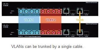
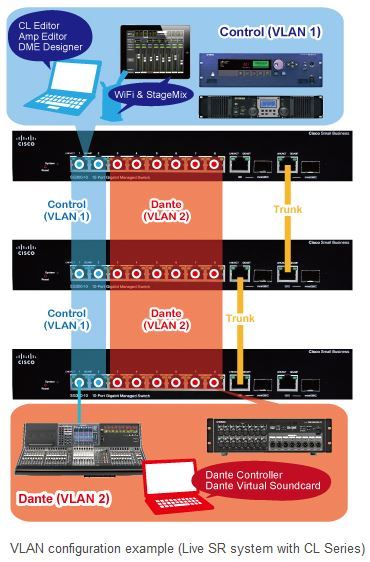
Now, typically we see trunk ports being used to interconnect network switches together to ensure that all of our VLANs
are visible to all of our network switches. All right, so now that we've got a basic understanding
VLAN Real-World Examples
of how VLANs work and some of the terminology in use, let's take a look at how you might be able
to actually configure VLANs in various types of equipment. I'm gonna start by showing you a few VLAN examples
that may be used in everyday life. One of the first things I should mention is that not all routers are going to be VLAN capable.
So for example, if you just go down to your local big box store and pick up some,
you know, Netgear something just right off the shelf, it might have like guest network capabilities,
but you're not able to add your own VLANs because they try to make these things as simple as possible.
So if you're in your router and you're looking for like, where are the VLAN settings and you're not finding them,
you might need to upgrade to some, you know, more prosumer or higher level of equipment.
Trunk Port Practical Example
So now let's look at a few different diagrams to help explain VLANs, both the untagged VLANs
and tagged VLANs, as well as trunk ports. We're gonna start with that trunk port. So what I have here is on the left-hand side,
we have our router. And in the router, again, this is just generic router, a generic router that has the ability to add VLANs
or separate VLAN subnets to the network. And here we can see that I have VLAN ID one,
that's gonna be our default VLAN or native VLAN, it's sometimes called. Then I added a guest network in green,
an IoT network in blue, and a VoIP or voice over IP network in red.
And what you can see here is that I have all of these networks traveling from the router
over to the switch, we can see all four colors. So I'm denoting each VLAN as its own color.
Now the switch has a trunk port. So the trunk port is receiving all VLANs that are sent to it.
So in this example here, with a trunk port that has the LAN untagged,
so the native default network is our LAN and it's untagged. And then we do have the capability of seeing the VLAN 10,
VLAN 20, VLAN 30 on that same network port. If I just plug in a PC, in this case,
it's like a Mac mini on the diagram, right? But if I just plug in a regular desktop PC that doesn't understand VLANs or like an IoT device
that doesn't understand VLANs, it's going to get an IP address in the default subnet, right?
Because it's not specifically looking for one of the tagged VLANs that's traveling along with that port.
However, if we see here, I have a voiceover IP telephone, that voiceover IP phone is configured to look for VLAN 30.
And since it finds VLAN 30 as one of the tagged VLAN port options on that port,
it's gonna configure itself into VLAN 30. It basically says, hey, here I am, I'm looking for VLAN 30.
And that port goes, oh, I know about VLAN 30. Here is your IP addressing information
for the VLAN 30 subnet, which in this case is 192.168.30.0.24.
Now I should mention that in this example, I am setting the VLAN ID equal to the third octet
in the slash 24 subnet for each of these different networks. You don't have to do that.
I just think that, you know, when I'm setting up networks, like logically, it makes sense to me to kind of make sure that the VLAN
is part of the network subnet that devices will get IP addresses from in that VLAN,
Untagged VLAN Real-Life Application
if that makes sense. All right, here's another example. So now we still have that trunk port that's carrying all VLANs over to the switch,
but I've now configured a different port for IoT devices. Right, so if I have some sort of wired IoT device,
like in this case, I have a Raspberry Pi, right? And say that Raspberry Pi is running something, you know, home assistant or something like that,
and I am physically plugging it into the network switch, but I don't want it to be in the default network.
I don't want it to be on my secure LAN. I want it to go into that IoT network that we set up.
So since that Raspberry Pi has not been configured to specifically look for a VLAN ID,
I'm gonna configure a switch port where the untag, the default network
when you plug something in that doesn't know about VLANs, the untag network is the IoT network.
Now I'm also on this same port, still carrying across tagged VLAN ID 30
for a voice over IP telephones. What that means is if I plug in an IoT device or any device that doesn't know about VLANs,
it's gonna get an IP address in the IoT subnet because that is the untagged or default VLAN for that port.
However, if I plug my phone in, which does understand VLANs, it's gonna say, hey, I'm here, I'm looking for VLAN 30.
And in this case, yes, we do see VLAN 30. So it gets an IP address in VLAN 30.
Enhancing Security with VLANs
All right, let's look at another example. So this is an example where all we want, anything plugged into the port
is going to be on the guest network, right? So remember our example from earlier in the video,
where you walk into a doctor's waiting room and you happen to see an exposed RJ45 ethernet port
just sitting there on the wall. If someone comes in, a hacker comes in and they plug something into that port,
we don't want them to have access to any of our secure doctor stuff, right? So depending on the secure doctor network,
we want them to only have a guest network as if they were connecting to the guest wifi.
Now it's guests only as untagged. So anything that's plugged in there
is going to get an IP address in the VLAN 10 network. But in this example, if I take my phone,
which is looking specifically for VLAN 30, and I plug it into that port
and if it only has untagged guest network on VLAN 10,
it is not going to get an IP address at all. Because it's going to say, hey, I'm a voice over IP phone,
I'm looking for VLAN 30. And the port's going to say, I don't know nothing about no VLAN 30, I'm so sorry.
You know, kick rocks. So this is how you can start to get really granular
with your security and basically say, look, if I've got an exposed port in a public area of my office,
I don't want to have any secure access available through that exposed ethernet port.
All right, last example. And then we are actually going to show you how to configure some of this stuff in different types of network equipment.
All right, so same concept here. We've got our four VLANs, all four are trunked across to this switch.
VLANs in Wireless Networks
And in this case, we're gonna set up a wireless access point and what wireless SSIDs are going to broadcast
from that access point? Well, we're gonna have one, we set up an SSID for the secure LAN,
we set up an SSID for our guests, and we set up an SSID for IoT devices
that need wireless access. And again, all of these networks, I'm not showing it in this video, but they should be firewalled off from each other
so that for example, the guest network can only see the internet, but it can't see any of the other networks.
The IoT network can only see the internet, but it can't see the other networks. And then our secure network, you know, if you want,
can have access to all of the other networks because that's your secure, your sort of main network. So in this case, what we do is we plug in our access point
and we tell the switch, look, we're gonna plug an access point into this port. I want the untagged VLAN for this access point
to be our secure VLAN, VLAN one, and it's gonna have an SSID of LAN.
Then we also want to have tagged VLANs of 10 and 20 because we also have wireless SSIDs for VLAN ID 10,
our guest network, and VLAN ID 20, our IoT network. Now, in this case, we only have hardwired voice over IP phones,
so I don't need to put the voice over IP VLAN tag into the access point
because it's never gonna get used. So now, if a PC or Mac that doesn't know about VLANs
connects up to the LAN SSID, it's gonna get an IP address in that network.
In fact, any of these devices, we're basically not dealing with devices
that know about VLANs at all for the purposes of this setup. It's just you're put on the correct VLAN
based on the wireless SSID that you actually connect to, and since we are pushing those VLANs into the access point,
it knows about the guest network, it knows about the IoT network, and it knows about our secure network. So whichever one of those SSIDs you connect to,
that's the network that you're getting placed into, and you'll get an IP address from the DHCP server.
UniFi VLAN Configuration
Okay, clear as mud, I'm sure. So let's now look at Unifi. So anyone who's a fan of this channel
knows that I am a fan of the Unifi ecosystem of products, and the way that VLANs work in Unifi is two steps.
In fact, this is kind of the same way that it works in any networking equipment. You've got the creation of the VLAN networks themselves,
and then you have which untagged and tagged VLANs
are traveling to each switch port in your entire network. All right, so from within Unifi,
if we come over here to settings, and then we click on networks, here you can see that I have set up my four different VLANs.
We've got the default VLAN, guest on VLAN ID 10, IoT on 20, and VoIP on 30.
So let's click into one of these, and you can see how I set these up. So basically, I unchecked sort of the autoscale network.
I don't like using that, so I can actually set the size of the subnet. If we scroll down a little bit further,
I set advanced to manual, and then that lets me enter in a VLAN ID.
Now, not related to actual VLAN functionality, but something that's super important for this type of setup
is the next setting right here, which is network isolation. So in the case of a guest wireless network, for example,
you're gonna have guests like at a restaurant or at a hotel that are connecting to that guest wireless, and you don't want those guests
to be able to see other devices on that same guest wireless network. So we enable client isolation,
which means that device that connected to that network can only see the internet. It cannot see other devices in that network.
However, if I pop over to my IoT network and we scroll down, notice that I don't have client isolation
on the IoT network. And why is that? Because in the IoT network,
we might want devices to talk to each other, right? So imagine the example of taking your smartphone
and streaming video over to a smart television or like an Apple AirPlay type of situation.
In that case, those devices within the IoT network do need to talk to each other.
Or for example, if you have some sort of smart light bulb setup where you've got like a Phillips Hue, for example,
has their little base station which connects to the network and it controls all of the light bulbs and whatnot
on that same network. So we do want devices within the IoT network to be able to communicate with each other.
We just wanna firewall those off so that they can't touch the guest network or the phone network or the secure network.
So once you've set up your VLAN with a specific VLAN ID, then in UniFi, they have what's called the port manager.
So if we come over here to the port manager and we click on VLANs, this gives us a graphical representation
of the untagged and tagged ports for every single one of our switch ports
in the UniFi ecosystem, right? We can pick which switch we're working with up here in the corner, and then these are all the ports associated
with that particular switch. So here we have port one, okay? So let's look at this.
In UniFi speak, blue means our default switch port,
our native network for that port. So if you plug a device in that doesn't understand VLANs,
this is the network it's gonna get put into. But then we have green, which is the tagged VLANs also as part of that port.
So port one is our trunk port, right? So we have default is untagged,
and then VLAN 10, VLAN 20, VLAN 30 are all tagged as part of that port.
If we now go back to our IoT port example, we can see that in our IoT network,
we want untagged VLAN 20 and tagged VLAN 30, because IoT devices that plug into that port
should get an IP address in the IoT network. But if we happen to plug a voice over IP phone that understands VLAN 30,
we want it to receive an IP address in VLAN 30. And here we can see that on port two.
So port two, VLAN 20 is blue, meaning that it is the native or untagged VLAN
for port number two on this switch. And then we also have VLAN ID 30 as tagged,
meaning it's riding along. If you know about VLAN 30, great, you can connect to it. Otherwise, you're gonna get the blue IoT VLAN 20.
Let's look at our next example, the guest port only example, right? Where you've got the doctor's waiting room
and you have an exposed network port in that waiting room. Anyone that plugs into that should get on the guest network.
In Unifi, that's gonna be our port three right here. So port three, notice that it's gray for default,
it's blue for the guest network, because that is our native or untagged VLAN for that port.
And then we are not carrying across any other tagged VLANs. So VLAN 20 is gray, VLAN 30 is gray.
So if you plug anything into port three, the only option is the guest network VLAN.
And if you have a device that understands VLAN tagging, like this phone that has VLAN 30 associated,
it's just not gonna work. And then finally, let's look at our access point example where we have the untagged default VLAN ID one,
and then we have tagged VLAN 10 for guests and tagged VLAN 20 for IoT devices.
In that case, it's gonna be port four. So there we have blue is our default VLAN ID one as untagged
and then we have green untagged VLAN ID 10 for guests and green untagged VLAN ID 20 for IoT devices.
Now, one of the things about Unifi is you could go through here and manually configure
every single one of your switch ports, but they also have a switch port manager or port profiles,
where if I knew that I was gonna have a bunch of ports that were that guest network only configuration
or the access point configuration, all these different sort of scenarios that I've been throwing out here,
you can set all of those up as port profiles, and then just assign the port profile to all of the ports
as opposed to doing it manually. So it just saves you a little bit of time by actually grouping the VLANs that you want together
and then assigning those to multiple ports simultaneously. Now let's look at the same exact VLAN setup,
Mixed Equipment VLAN Setup
but this time we're gonna be doing it with like a mishmash of equipment and I'm actually gonna be plugging stuff in
so that you can see IP addresses change and whatnot. So in this case, I have this Synology RT6600AX,
and this is kind of like a prosumer home router, one with all the thousands of antennas on it and whatnot.
And then I have this more like enterprise level Aruba 24 port switch with PoE.
So you can do VLANs with a mix of equipment, assuming that all of the equipment
that you're working with understands VLANs. VLANs are a standard, right? They're gonna be the same across anything,
like the nomenclature might be a little bit different, the buttons you have to press and the menu items you have to surf around to might be different
from equipment to equipment, but it's all generally gonna be the same concepts.
So I'm logged into the Synology router and I opened up the network setting and I clicked on local network here,
and this is where we can add additional VLANs. Now, interesting thing about this Synology router
is that while we can actually add different VLANs, here you can see I've got primary network, guest network,
IOT network and VoIP network. And if I click into any one of these and hit edit,
we can see the VLAN ID is assigned right there, as well as all of the networking information up above.
But the interesting thing about this Synology router is if I click on VLAN tag,
you unfortunately only have two options for VLAN tagging. You can make each of the ports in the back of the Synology
of which there are four, you can make those ports trunk ports, meaning that the primary network is the untagged VLAN
and any other VLANs you set up are traveling alongside as tagged VLANs,
or you can set up a single VLAN only. So like if you look at ports one, two and three here,
I've got my primary network untagged across all of those, and then I've got the guest VoIP and IOT network
tagged across all of those. But port four, I called VoIP, and I just did an untagged VLAN 30,
which is my VoIP network for that fourth port. So anything you plug into that fourth port is just gonna go straight onto VLAN 30.
Connected over to this Aruba is port one, right? So the trunk port that goes over to the Aruba
and in the Aruba, I have both ports one and two configured as trunk ports. So let's take a look at that next.
Synology RT2600ac VLAN Setup
So I set up all of the VLANs in the Synology RT6600AX.
And then when I first logged into this Aruba switch, I also have to tell this Aruba switch about VLANs, right?
Aruba 1930 VLAN Setup
So it doesn't know about any of those VLANs by default, I actually have to tell it about those VLANs. That's one of the disadvantages
with working with a mishmash of equipment. Typically, you have to configure each different piece of equipment
to understand the VLANs that you're feeding into it. Whereas with something like Unifi, you just set it up in that one console
and your routers and switches and access points, they're all gonna know about your VLANs because they're all sort of configured in the same place.
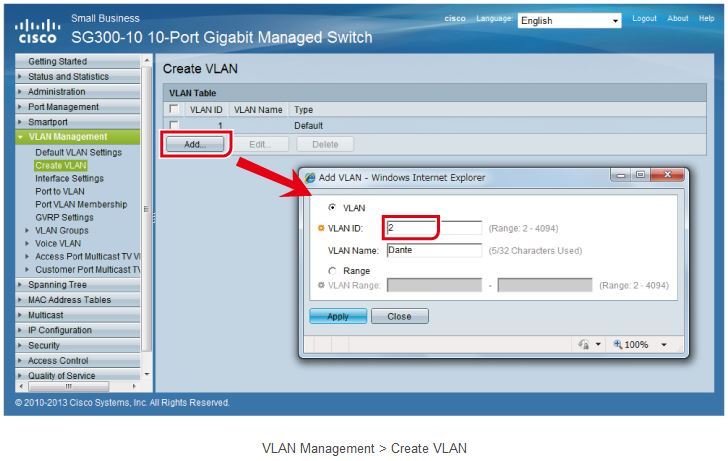
So if I come over here to VLAN and VLAN configuration, this top section here is where I can add VLANs.
It's as simple as just clicking Add, and then you give it the VLAN ID and you give it a friendly name.
It can be anything you want. And so I did that three times to create VLAN ID 10 for guest,
VLAN ID 20 for IoT and VLAN ID 30 for VoIP. So we've now told it about all of our VLANs.
And of course, the VLAN ID one is the default or native VLAN by default.
And if we scroll down here, we can see VLAN membership by interface.
And once again, just like Unifi, where we had the blue for untagged and green for tagged,
we don't have colors here, but we can see untagged VLANs here, and we can see tagged VLANs over here.
Remember, I said the first two ports on this switch are essentially trunk ports, right? So we have untagged VLAN one,
and then I have 10, 20, 30 as the tagged VLANs. Now, if I wanna edit this, I can just select one or more ports and then say Edit.
And it basically shows me what to do, right? What is the untagged VLAN? I can select one and then I can say,
what are the tagged VLANs? And it gives me the sort of syntax of tagged VLANs down below.
Now, going back to our IoT example, where we have untagged VLAN ID 20,
but tagged VLAN ID 30, in case we wanna plug a phone into that port, you set it up like this.
Edit, untagged VLAN is 20, that's our IoT network,
tagged VLANs 30 only, right? So now, no native VLAN access
and no guest network access on this particular port. So let's test that out.
VLAN Testing
Right now, my PC here is plugged into port one, meaning that it doesn't know about VLANs,
so it should have an IP address in the default network of 192.168.1.x.
Let's double check that. If we run ipconfig here, we can see 192.168.1.192 is the IP address of this computer.
Now, if I unplug this computer from port one and plug it into port three, which is our IoT setup,
once it gets its IP address, if we now run ipconfig again, look at that.
Now the IP address is 192.168.20.192.
However, if I unplug my computer, plug it back into port one, and then I take my voice over IP phone here
and I unplug it and I unplug this into, or I plug the voice over IP phone into that same port.
Remember, this is the port where I just plugged in my computer and I got 192.168.20.192.
I have now plugged in the voice over IP phone and once this boots up, we'll take a look at the IP address.
This, by the way, is the Crosstalk 280. It's absolutely a gorgeous phone and it's Android-based
and it has a camera built right in, so you could do Zoom calls and Google Hangouts, as well as just phone-to-phone video conferencing,
plus it still has all the tactile buttons down below. I love this phone. Okay, so it just connected and it is registered,
so I know that this phone can see the internet, no problem, and if we come over here to settings and network
and click on IPv4, the phone's IP address is 192.168.30.125.
Let me grab some video of that because I know it's gonna be impossible to see. There you go. The IP address, 192.168.30.125.
So that is successful, right? My computer that doesn't know about VLANs plugged in and it got an IP address in the untagged VLAN for that port
and then my phone, which does know about VLANs, I plugged in and it got an IP address
in the VLAN that was tagged on that port because this phone knows about it and specifically asked for an IP address
in that other voice over IP, VLAN. All right, now we have our guest port example, right?
So in our guest port, we only have untagged VLAN 10 on the port and nothing else.
So I set that up as port four. Let's take a look at it. So port four here we can see, untagged VLAN 10
and no tagged VLANs at all riding across that port. Let's go ahead and unplug our laptop
and we're gonna plug it into port four and the network is connected. Let's do ipconfig and the IP address is 192.168.10.192.
because it's in the guest network only. Now, if I plug my phone into that port, it's not gonna get an IP address at all
because it's asking for VLAN 30 and that port doesn't carry VLAN 30 as untagged or tagged.
So that's it. And now let's look at our final example where we have our access point plugged into a port
and that port has the LAN network, the secure LAN untagged,
the guest network tagged as VLAN 10 and the IOT network tagged as VLAN 20. All three of those networks are traveling across here.
And then this is broadcasting out three different SSIDs. Each SSID is associated with a different VLAN.
So when you connect on whichever SSID, that's the IP address you're gonna get. You're gonna be placed into that specific network subnet.
Conclusion
So there's VLANs made easy and hopefully this video helped to demystify VLANs
and you can now be confident enough to start playing around with them in your own networks.
And remember, if you get stuck on any VLAN configuration or if you just want to have us
do a complete network design for you, open up a ticket at Rogue Support and we'll make sure that you're well taken care of.
If anything is still unclear or if you have questions about VLANs, pop those down into the comments below
and I will do my best to get them answered. And if you'd like to keep this party going, I have hand selected a couple of videos on the right here
for you to watch next. The top video is my recent review of the Starlink Gen 3 Dish and Internet Service.
And the bottom video is my unboxing of the new Pro Max network switches from Ubiquiti,
which feature RGB ether lighting. You can actually configure those switches to show you VLANs in different colors
right through the switch ports. Really cool.