
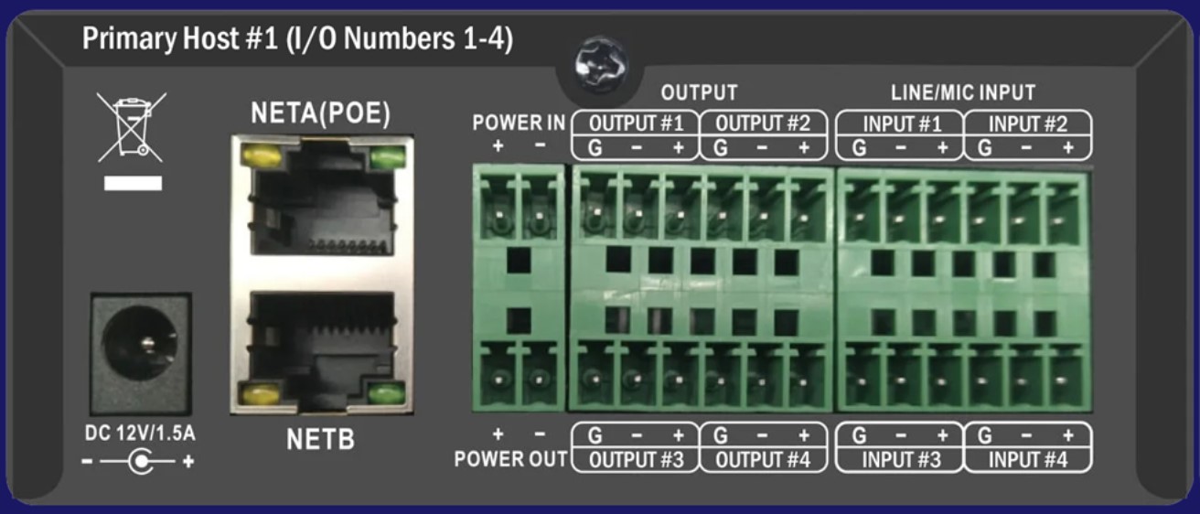
Allonis's new DSP444 is a Digital Signal Processor that is often configured as an audio matrix. It support 4-Analog Inputs and 4-Analog Outputs. It also supports digital audio using the AES67 audio specification. This allows the DSP444 to digitally share it's Inputs to a second (or third....) DSP444 so the system is near infinitely scalable. Allonis can provide devices with 4, 8 or 28 digital channels. Advanced DSP features are disabled when 28 digital channel firmware is chosen.
Audio Capabilities:
| Sample Rates | 44.1/48/88.2/96 KHz |
| Network audio latency | 1 ~ 10 ms |
| Bit Depth | 24 Bit |
| Channel isolation | 84DB, A weighting, re+4dBu |
| Frequency response | ±0.3DB 20Hz-20kHz |
| Maximum input/output level | 14DBU@1kHz, THD+N≤1% |
| Dynamic range | 110DB, A weighting |
| Words put gain | 0\15\20\24 DB 4 files |
| Common mode rejection ratio | ≥50DB @1kHz, re+4dBu |
| Harmonic distortion + noise | 0.005%@re +4dBu, A weighting, 1kHz |
| MIC Current (mA) | Phantom Output Voltage |
| 1 mA | 39.2 V |
| 2mA | 30.4 V |
| 3mA | 21.6 V |
| 4mA | 12.8 V |
Hardware:
|
Analog audio channel |
4 IN, 4 OUT |
| Network audio channel | 4 IN, 4 OUT |
| Power supply | 12VDC, 1.5A, PoE power supply |
| Phantom power supply | 48V, 10MA, Ripple≤10MV |
| Analog Interfaces | Phoenix Interface |
| Network | 100Mbps |
| Size | 108*149*45mm |
| Net weight | 0.7 kg |
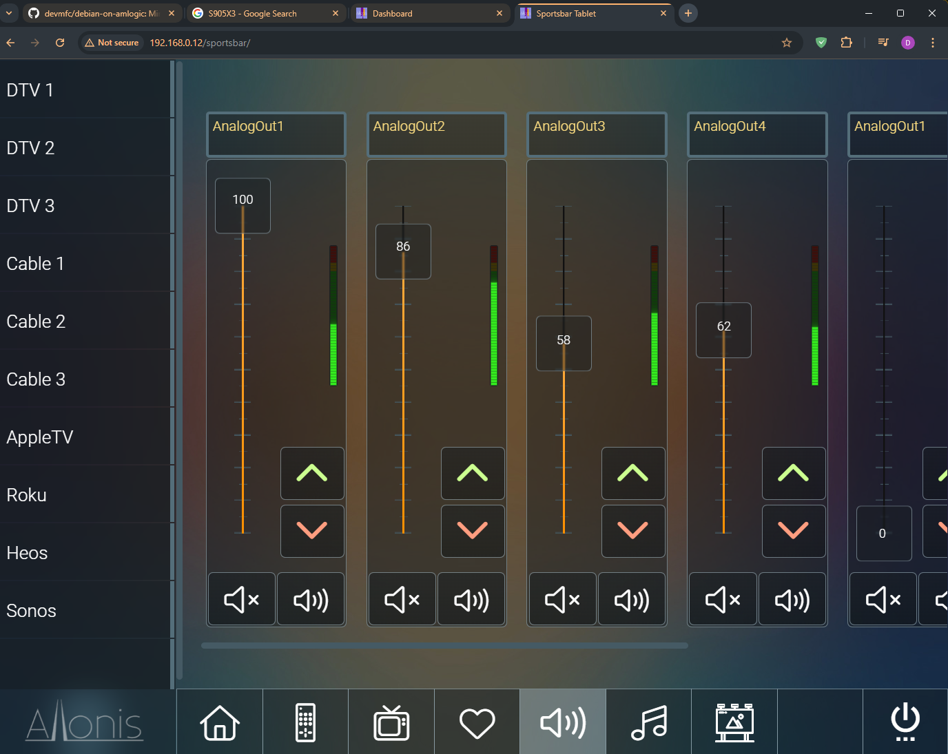
The myServer 6 driver is very comprehensive in it's support. You can setup an audio matrix system, including michrophone ducking, and page steering. It is intended as an end user interface, not an audio engineers interface due to it's designed simplicity.
A key feature is AES67 is also compatible with Dante digital audio when Dante is broadcasting in multicast mode. So, the list of supported compatible hardware is huge.
Model Feature Comparison table
| DSP Function | DSP444 | DSP4428 |
| PEQ | ✔ | ✔ |
| High/Low Shelf | ✔ | ✔ |
| High/Low Pass | ✔ | ✔ |
| Delay | ✔ | ✔ |
| AFC | ✔ | ✔ |
| 96KHz | ✔ | ✔ |
| Compress | ✔ | ✔ |
| FIR | ✔ | ✔ |
| Noise Gate | ✔ | ✔ |
| Peak Limit | ✔ | ✔ |
| AEC | ✔ | |
| AGC | ✔ | |
| ANS | ✔ |
Installation
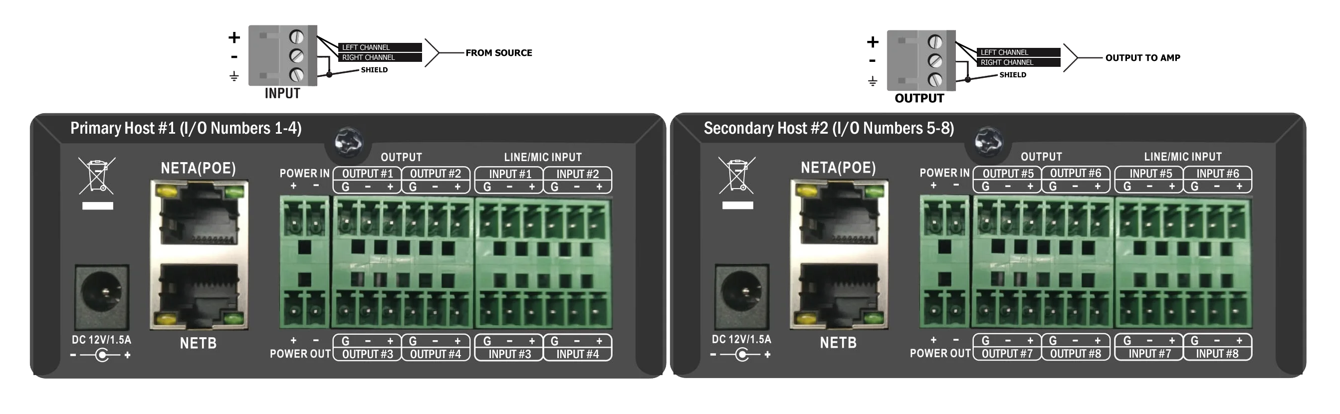
In most Allonis's systems, recommended is to use the 1.5U modular case to house the DSP444 (one to three per rack case). A typical bar system would be myServer 6 automation controller on the left side, and a 4x4 DSP444 on the right side of the case. The "Z" bracket gets mounted to the front of the DSP444 which gets screwed to the bottom of the modular case. The back panel gets attached by the single center screw on the connector side of the DSP444. Looking from the back, the Left Most DSP is "Primary" and the one to it's Right would be "Secondary". This standardization is important for system addressing.
You can also put the DSP444 on a shelf. Because the DSP444 shares audio sources via the ethernet connection, the DSP444 can be located in a second location that is ethernet connected.
Each DSP444 must be connected to the "audio ethernet network" VLAN on a managed switch. This network can be dedicated to just audio, or can be shared with the "Control Network" since audio doesn't really consume huge amounts of network bandwidth like digital video does. Use (for example) a "Ubiquity" Or Allonis brand quality L3 managed network switch with AES67 prioritized data packets to minimize chance for "choppiness" in the audio feed.
By default, the DSP gets it's initial IP via the DHCP server on the network. They communicate (and can be discovered) via UDP on port 8999.
Power
Each DSP has Net A that is POE capable. This is the recommended port so you can remotely manage the power via a Managed switch POE settings. Also, the Managed switch should be connected to a robust UPS so then the DSPs are also protected by the UPS.
The DSP also has Net B that is Not POE. You can use this port on a non POE switch, and use the wall power supply to power the DSP.
You should not use both POE and the wall power as that might introduce a ground loop noise issue.
If analog device connections need to be changed...it is HIGHLY recommended to power down the DSP444 prior to disconnecting analog signals.
Multiple DSPs
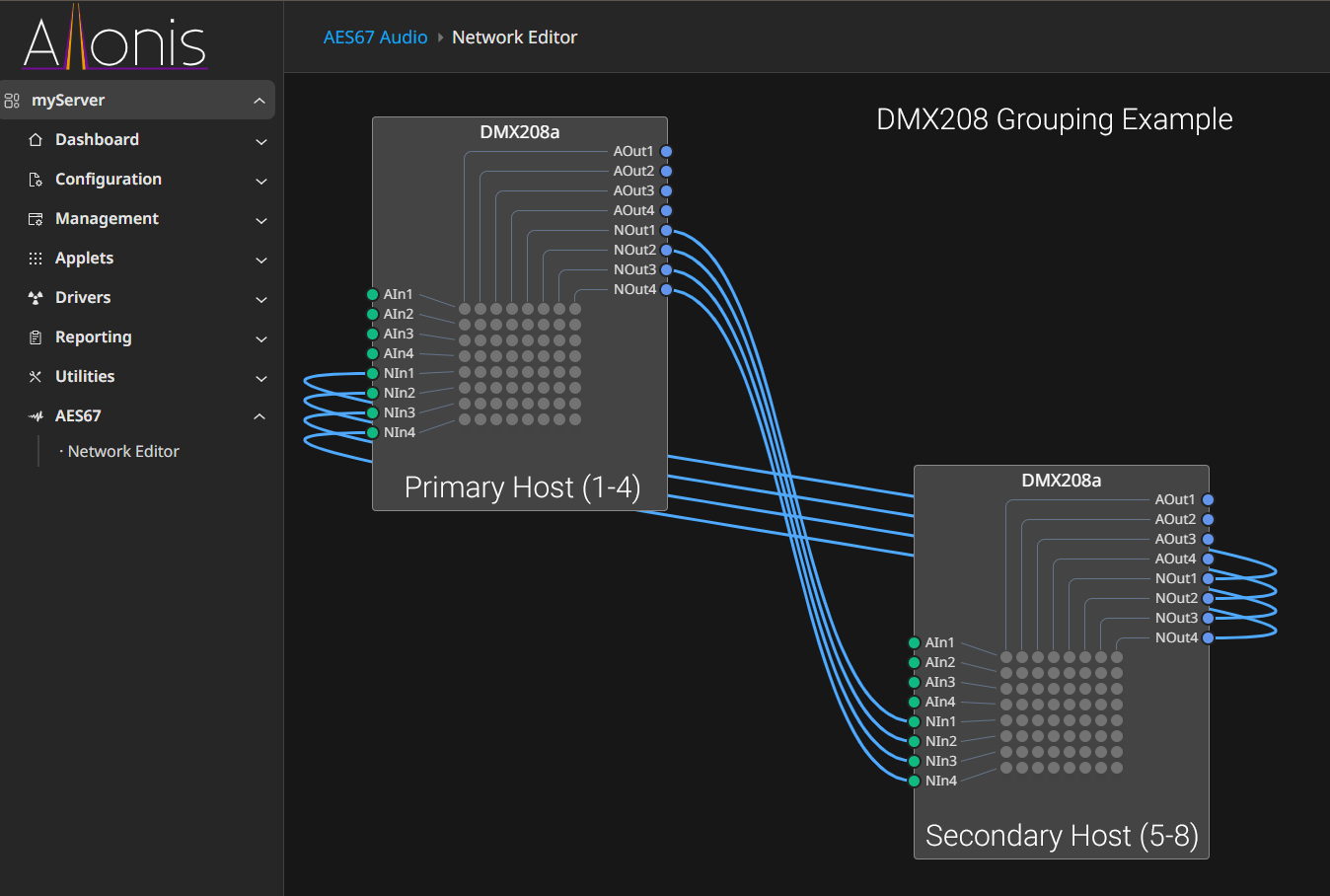
To give you a visualization of how the two DSP's need to work together. The first is a logical network view of how they are wired. The second is a view from the DSP router's perspective. In order to get the analog signals from each DSP to its partner the analog signals must be routed via the network ins and outs. We'll end up with a logical 8x8 analog switch but there is a lot of steering logic happening in the driver.
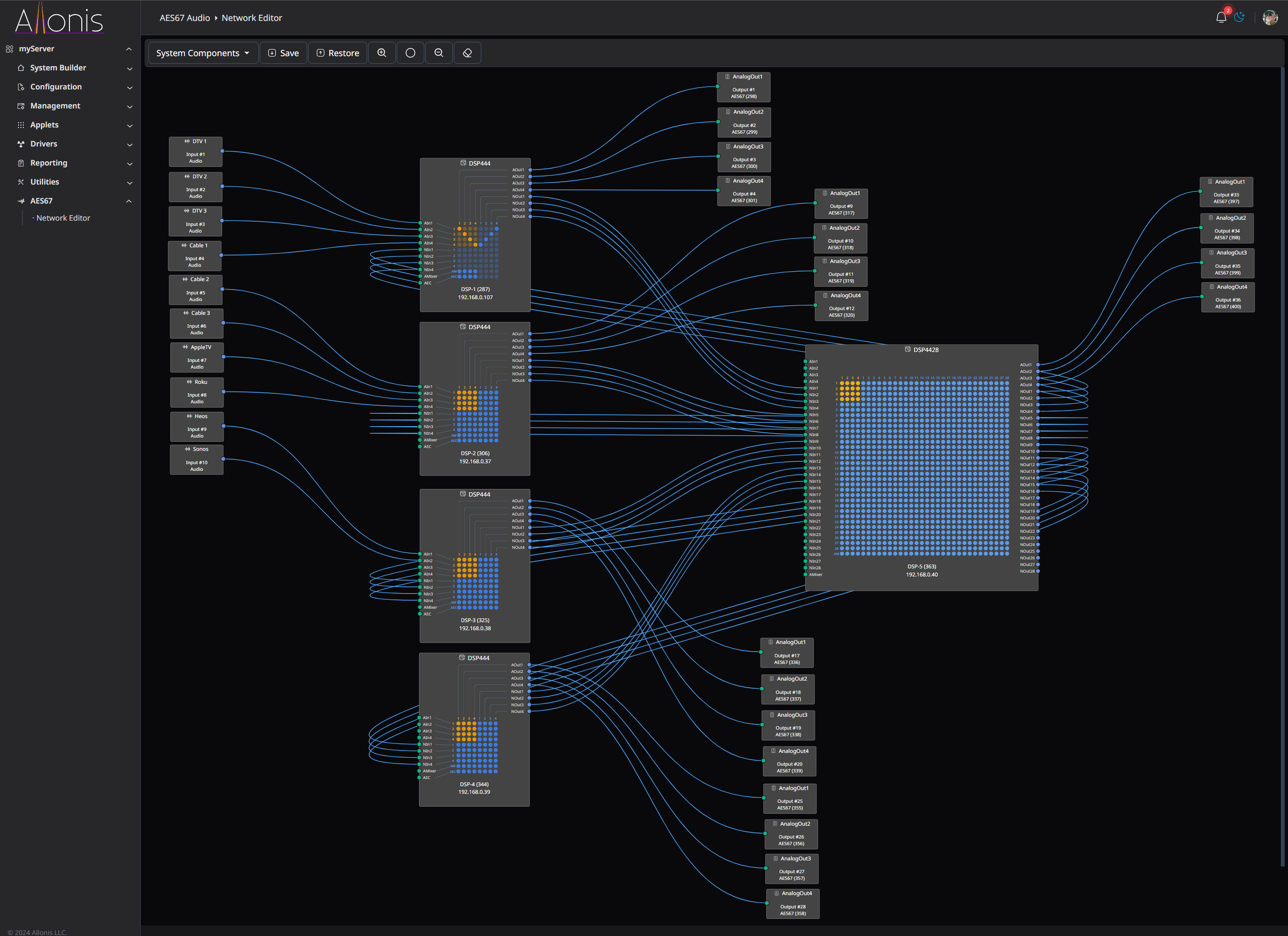
Once you need to Group more than 8 analogue inputs or outputs, you need a DSP4428 to increase the number of digital audio channels that can share the analogue signals to additional output routes.
Networking
You can increase the latency in each DSP444
It is necessary to increase the latency of data packets in the network settings to prevent untimely delivery of packets, which may cause each processor to discard them.
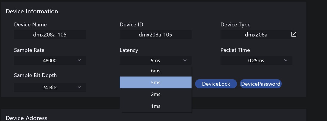
Alternatively, there might be other mixed devices on the network, such as CCTV cameras, that require raising the priority of audio stream data packets. This can be set in the "Status" settings.
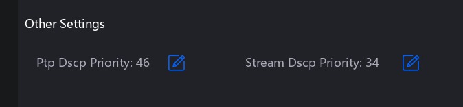
The higher the number, the higher the priority.
You can configure inter-VLAN communication on the switch. As long as you can ping through, audio unicast streams can be transmitted. If you need to multicast across subnets, you will need to configure PIM-DM on a management switch.
Open the DSP444 packet arrival schedule to check if there are any red bar graphs indicating packets that did not arrive on time.
Audio Wiring
Most all commercial projects and hallways in residences are wired Mono. This is because people walking around aren't equidistant between two stereo pairs of speakers. Most audio sources are stereo. So, the source audio outputs have to be connected together to achieve a mono signal.
Lets assume your audio source devices use "RCA" jacks. There is a Tip (signal) and a Shield (ground) to the connector. Fashion a wiring connector that connects the Left and Right Tip together, and connect that to the DSP444 Analog Audio Input Positive. Then, tie the grounds together and connect that to the same Analog Input channel's Ground AND Minus.
If you have balanced connectors then you will have the three discrete wires (plus / minus / ground). Connect these to the respective Phoenix connectors that plug into the DSP444's inputs.
The rest of the system uses one channel for each zone (which is mono). One amplifier channel is connected to one DSP444 Analog audio Output. Wire these same as the Inputs (positive tip / Ground and Shield together).
Configuration
Note that myServer needs to be on the same subnet as the DSPs and subscribed to the same VLAN (Allonis typically uses VLAN 30).
In the AES67 driver, select the command Set Multicast Interface and choose the ethernet NIC your myServer controller should use to connect to the AES67 network: "AES67|SetMulticastInterface~vlan30" as example.
When your DSP hardware is powered and on the network, click Discover for myServer to find your DSP devices. In a few minutes, Discovery should find all DSP devices on the network. You can click Discovery again to shut off the process. Post Discovery, restart myServer and on restart, go back into the driver's configuration. Click on Matrix view (bottom of the Driver Command Testing page).
Name your Audio Sources in the Commercial Audio tab under Management
Create DSP Groups in the AES67 driver
Restart myServer
Name the Analog Outputs (ie: Bar / Dining / Patio / Rest Rooms etc) in the AES67 driver
Physical I/O is the actual named ports on the DSP. Logical I/O describes what the system uses for inputs and outputs. So, in an 8x8 system (2 DSP 4x4s), there are two sets of Physical ports. There is one 1-8 set of Logical ports.
We will call the first DSP the "Primary" and the second (ports 5-8 as "Secondary") Host.
The Host can be thought of as the device that has a ethernet NIC (the RJ45 jack). The children of that Host come directly below that. Inputs are listed, first, followed by Outputs. Within Inputs, the analog Inputs show up first, followed by the network inputs.
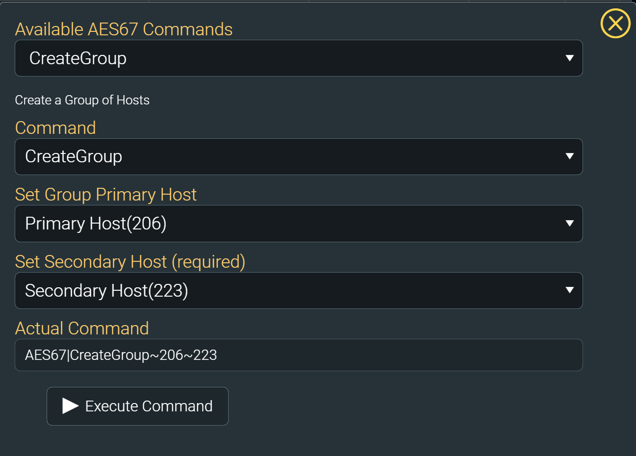
You will need to identify the two controllers. one must be designated primary and the other secondary. the use the drivers "CreateGroup" command to pair the 2 controllers. once paired you will see audio outputs 1..4 on the first and 5..8 on the second
Click on Network Routing View.
If audio routes have already been configured, you should see check marks on what Outputs are playing what Inputs (sources). You can change those routes by clicking in the appropriate empty box, to command the system to change which sources the Outputs are playing. Note that is you have more than one DSP444, that you can route "Source1 Analog" to "NetIn1" on the Secondary DSP (Secondary "host"). This then shares the Primary Source1 to the Secondary DSP444 host.
Audio Issues If a display on an output using 2-channel stereo audio is switched to an input with an EDID set to surround sound audio format, audio at the display speakers may be garbled, missing pieces of the audio track, or muted altogether. This symptom indicates that the display cannot down-convert the audio stream from the source. To fix this issue, the source must be set to output only 2-channel stereo audio.
Matrix View
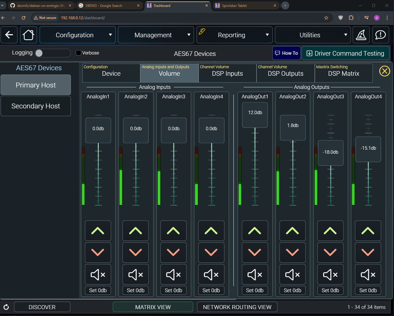
Volume tab
Best strategy is to change Input volume(s) to balance the sources to be same volume. The Analog Outputs shoudl be used to change the volume in a "Zone" ie: don't use the Analog Inputs for most cases.
DSP Inputs Tab
Suggested is to leave these at 0.0db (100%) for most system setups.
DSP Outputs Tab
Suggested is to leave these at 0.0db (100%) for most system setups.
DSP Matrix Tab
Displays the volume settings for both Inputs and Outputs. It also displays current routing of devices. If you click on the table cells, the routing commands will be sent to those devices. If you have two or more DSP444's setup in Group mode - high recommendation not to change anything in these routings or it will break the group definitions.
Mixing
Click the mixing checkbox. This allows to you put two (or more) sources to one output blended by your Input settings. The volume numbers in each cell are the Mixer volumes. A UI will be developed soon to enable editing those settings.
Network Routing View
All of your AES67 Discovered devices should populate this dynamic table. If your devices are grouped ("two DSP444s grouped becomes one 8x8 matrix"), making changes here will change those group definitions.
Subwoofer Support
Subwoofer cross over points, ramp rates, etc are supported within the DSP444 hardware. Contact Allonis to get the Windows configuration application that can set this up as today, those functions are not built into the myServer 6 driver.
Grouping DSP444(s)
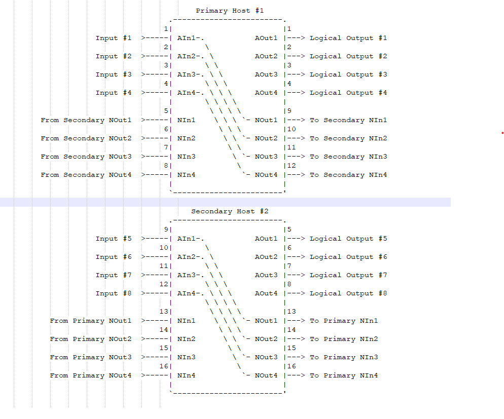
There are 6 different AES67 configurations supported that will create an audio matrix in 4x4, 8x8, 12x12, 16x16, 20x20 and 24x24 geometries.
Devices (hosts) will be named DSP-1 to DSP-n.
Since each DSP444 or DSP4428 are standalone devices, they will be discovered in a random order and their default input and output numbering will also be defined by the order they are discovered. By itself this leads to chaos.
To bring sanity into play these devices must be logically grouped to define a single matrix.
The driver has a CreateGroup command that will be used for this purpose.
There MUST be a standardization on the physical layout of these devices as they sit in the chassis and have a way to map them to DSP-1 to DSP-n.
Please review the attached spreadsheet as it has a tab dedicated to each proposed DSP configuration.
The customer is only interested in input and output numbers and you’ll see that each configuration keeps those numbers in sequential order.
The driver needs to work with the network inputs and outputs as well as the analogs but these I/O numbers are not exposed to the user. We use our own private numbering scheme for them.
The inputs labeled AMixer are how ducking is controlled.
Background:
AES67 devices communicate using UDP multicast.
Here is a command to see those packets on the network
sudo tcpdump -i br0 | grep 239.0.0.
Advanced Functions:
Ducking:
Pay for music in the Jukebox, and the audio coming out of that player takes priority over all other audio sources (like DirecTV audio). Pick up the microphone and start speaking, and that overrides even the Jukebox (example of ducking prioritization).
Selectable priority, ramp down volume rate of the secondary audio, ramp up rate, Threshhold of how loud the priority audio needs to be before switching Ducking, Time that priority keeps the priority even if no volume, are configuration that need to be set to define the Ducking performance.
Page Steering:
Page Steering: This is the ability to choose a room, and have the Michrophone Duck the audio devices in that room. Take the same michrophone into a second room, click on the myServer user interface to use the michrophone there, and the Ducking will work in that chosen room.
I. Products
Thank you for purchasing DSP444 / 448/ 4428 network audio processor. This processor features high integration, excellent performance, easy expandability, flexible control and so on.
1.Functional features
- Sampling rate: 48 KHz / 96KHz
- High-performance AD/DA, low distortion, large dynamic sound purity.
- AES67 RTP network audio, efficient and simple, easy-to-use operating interface software ‘Digisyn Link3’, real-time control of all functions and monitoring of each device’s working status.
- 4 MIC/LINE inputs & 4 balanced outputs.
- 4 AES67 network inputs & 4 AES67 network outputs.
- Each input has adjustable sensitivity (0dB/15dB/20dB/24dB) with independent 48V phantom power control.
- Input and output audio signal gain is independently adjustable, with a range from mute to +12dB.
- Supports 2 gigabit network ports, each capable of transmitting both communication and audio data simultaneously; supports POE-AF power supply.
- Supports power LINK interface for daisy-chaining multiple units, making installation easier.
- The panel features 14 LED indicators for audio and system status, along with a phantom power switch for user-friendly interaction.
- Up to 4 units can be expanded into a 1U rack mount installation, with mounting holes designed on the panel.
2. Front panel function diagram
- 【Channel level indicator】:
- [IN1] \ [IN2] \ [IN3] \ [IN4] corresponds to the input signal indication.
- [OUT1] \ [OUT2] \ [OUT3] \ [OUT4] corresponds to the output signal indication.
- When the input/output reaches a certain amplitude, the indicator lights up.
- Red is displayed when clipping.
- 【POWER indicator】: the red light is always on after powering up.
- 【SIGNAL】 Network communication status light: If both network ports are disconnected, the indicator light will flash orange; otherwise, it will flash green.
- 【Phantom Power】Phantom Power Indicator: [MIC1] \ [MIC2] \ [MIC3] \ [MIC4] Indicates whether the input channel is on phantom power.
- 【Phantom Power Button】: Switch for phantom power of each input channel.
3. Rear Panel Schematic
- 【DC 12V/1.5A】Power input socket: DC jack, 12V 1.5A.
- 【NETA (POE)】【NETB】Gigabit network interface: Two channels A and B. Used for control and audio transmission. Channel A supports POE.
- 【POWER IN】Power link input interface: daisy chain power input.
- 【POWER OUT】Power link output interface: Cascaded power input in a daisy chain.
- 【Input audio channel】 Supports microphone and line input. Balanced or unbalanced type.
- 【Output audio channel】Balanced or unbalanced output.
4. Schematic diagram of system connection
II. Functional description
1. Equipment start-up
- Connect the adapter or POE power supply (not both); the power indicator on the front panel will light up.
- The device will begin to start the system, taking approximately 20 seconds.
- Once the startup is complete, the SIGNAL indicator will flash, indicating normal operation (flashing green when connected to the network, flashing orange when not connected).
2. Microphone phantom power switch
- This device supports up to 4 microphone input channels, with independent control for each channel's phantom power switch. The 【Phantom Power】button is used to select the channel; pressing it once will cycle through the selected microphone channels, with the chosen channel flashing a red light. If no operation is performed within 5 seconds after selecting a channel, the setting will exit.
- On/Off Phantom: After selecting a channel using the [Phantom Power] button, a long press of 3 seconds will toggle the phantom power on/off state.
3. Restore factory settings
To restore factory settings, after the device has started normally, press and hold the [Phantom Power] button for 10 seconds, then release it. All panel lights will illuminate red and turn off after 2 seconds, indicating that the factory reset was successful. The device will need to be manually restarted afterward.
4. Equipment Search
In the normal state, the device corresponding to the press and hold [Phantom Power] button. Release after more than 5 seconds, GUI interface is highlighted in blue.
III. Computer interface software communication control function
1. Equipment connection
The computer running the software needs to be connected to the same local area network as the device and must be able to communicate with it. After launching the software, it will automatically search for devices on the local network. Once a device is found, you can configure parameters, set routing, and check the device status.
2. Equipment information
Clicking on [Device Infor] section will display information about all online devices within the local area network, including device ID, device type, device name, IP address, clock status, PPM, clock master/slave mode, clock priority, version, and more. This information can be used to assess the operational status of the devices.
3. Equipment parameters
Clicking on [Device Parameter] in the function bar will display the parameters of all online devices in the LAN, including sampling rate, packet time, network latency, running time, etc., which can be used to analyze the device connection.
4. Equipment parameter setting
In this window, the parameters of the device can be viewed and modified.
4.1 Analogue input/output settings
In the Channel Volume column, you can view the level status of the analogue input/output channels, set the gain and mute of each channel.
4.2 IP address settings
In the [Device Config], you can view the IP address of the device and configure fixed IP, automatic IP and other methods.
5. Description of DSP function usage
5.1 Description of DSP functions
5.1.1 Channel selection
The top bar indicates the currently displayed channel, AnalogIn 1-4 indicates the analogue input channel, NetIn 1-4 indicates the network input channel, AnalogOut 1-4 indicates the analogue output channel, NetOut 1-4 indicates the network output channel. Click switching channels to set parameters for different channels.
5.1.2 CPU usage
In the upper right corner, the CPU usage rate will be displayed, showing two values separated by a "-". Each value can be a maximum of 100. When both values are relatively high, it indicates that CPU usage is high (it is recommended to keep it below 85%). Be mindful of resource limitations when using actual functions.
5.1.3 EQ function settings
Each channel supports multi-band PEQ function, for each band EQ you can set gain, type (P/HS/LS), frequency, bandwidth and bypass separately and other functions.
Click on "Graph" on the left, you can expand the graph to see the equilibrium of the corresponding curve illustration, again click on the hidden screenshot.
5.1.4 Volume Gain Settings
The Volume function allows you to set the gain value for the corresponding channel and also provides an option to mute.
5.1.5 Level display
The Level function allows you to view the amplitude of the corresponding channel, with the level dynamically refreshing in real time.
5.1.6 High and low pass settings
The HighPass/LowPass function allows you to set the parameters for high-pass and low-pass filters, including frequency and type. "Flat" indicates no effect. You can click on "Graph" to view the corresponding curve.
5.1.7 Delay, Feedback Suppression Settings
- The Delay function allows you to configure channel delay, ranging from 0ms to 100ms. A maximum of 4 channels can have delay configured.
- The FBE function configures the feedback suppression level when using microphone input. It is turned off by default; the higher the level, the stronger the feedback suppression, but the more noticeable the impact on sound. The range is OFF and levels 1-3.
5.1.8 Noise gate settings
The Noisegate function allows you to set the noise gate for the corresponding channel. You can configure the following parameters: Noise Db, Open Time (the time it takes to open the gate), and Close Time (the time it takes to close the gate).
5.1.9 Limiter settings
The Limiter function allows you to set a maximum level limit at the specified value. You can configure the trigger threshold (Limit Trig) and the limit threshold (Limit Up). When the detected level exceeds the trigger threshold, the limiter will activate, ensuring that the processed level does not exceed the limit threshold.
When this function is active, it may cause distortion and is generally used as a protective limiting feature.
5.1.10 Compressor settings
The Compressor function allows you to set the following parameters: Threshold (threshold level), Attack Time (Atk Time), Release Time, and Ratio.
5.1.11 FIR settings
The FIR function allows you to set parameters such as FIR type, window type, and FIR taps.
5.1.12 Matrix settings
The matrix can be set to correspond to input channels and output channels for flexible configuration and use.
5.2 Echo cancellation, auto gain, background noise reduction (optional features)
5.2.1 Echo Cancellation AEC Function Description
- The AEC function is used during remote meetings to eliminate echo caused by microphone pickup and amplification.
- AEC requires selecting the Near input signal (microphone input channels) and then selecting the Far input signal (AEC signal transmitted from the remote end) before transmitting the AEC signal to the remote end.
- Al-A4 refers to the device's analog input channels 1-4, while Nl-N4 refers to the device's network input channels 1-4. The Near signal can select multiple channels (in cases with multiple microphones), and these channels are mixed before entering AEC processing.
- The Far signal can also select multiple channels (in cases with multiple remote meeting rooms), with these channels mixed before entering AEC processing. AEC is set to OFF by default, with levels ranging from 1 to 11; a higher level indicates stronger echo cancellation capability but also greater impact on sound quality.
5.2.2 Automatic Gain AGC Function Description
- The AGC function automatically adjusts the gain for signals on the AEC channel.
- AGC is set to OFF by default and has only two states: OFF/ON. This function is only effective for AEC channels.
5.2.3 Background noise reduction ANS function description
- The ANS function processes background noise on the AEC channel, reducing specific background noise.
- ANS is set to OFF by default, with levels ranging from 1 to 4; higher levels indicate stronger noise reduction capability but also a greater impact on sound quality. This function is only effective for AEC channels.
5.2.4 Single Microphone Individual Remote Conference Room Wiring Diagrams
5.2.5 Multiple Microphones Multiple Remote Conference Rooms Wiring Diagrams
5.3Configuration saving and importing
5.3.1 Opening the configuration screen
On the DSP page, click the "Save & Load" button to open the configuration page.
5.3.2 Current use configuration
Current Config shows the name of the current configuration file loaded by default on boot.
5.3.3 Saving the configuration
After modifying the DSP parameters, they will be automatically saved. If you need to save the configuration to a file, you must manually select the desired configuration name in the Config List and then click “Save” to store the configuration.
5.3.4 Loading Configurations
If you need to load a certain configuration file, select the name of the configuration you want to load in the Config List and click “Load” to load the configuration.
5.3.5 Deleting Configurations
If you need to delete a configuration file, select the name of the configuration you want to delete in Config List and click “Delete” to delete the configuration.
5.3.6 Importing configurations
To import a configuration file, click Import and select the correct external file to import its settings into the device. If you want to save the imported configuration for future loading, you need to manually click “Save” to save it.
5.3.7 Exporting Configurations
To export the configured settings to a file, select the desired configuration name in the Config List and click “Export” to save the configuration file to your computer. The exported configuration file can be imported again or transferred to another computer for use.
5.4 DIY DSP Functions
5.4.1 Opening a DIY DSP Page
On the DSP page, click the "DIY" button to open the DIY configuration page.
5.4.2 Selecting channels
The DIY page allows you to customize configuration settings for each channel. Select the desired channel at the top, and then configure the corresponding channel functions.
5.4.3 Selection functions
Clicking the "+" icon allows you to select the desired functionality from the pop-up window to add it. Each "+" icon can be configured for one function, and the order of selection does not matter; selecting a function earlier or later will yield the same result. If you want to remove a specific function, click the button again and choose the last option "Empty" in the pop-up to remove the corresponding function.
5.4.4 Channel Copy (COPY FROM)
If you want to copy the entire configuration from one channel to another, select the channel and then click "COPY FROM." In the pop-up window, choose the name of the channel you want to copy from.
5.4.5 Evaluation of CPU resources
The DIY function offers flexible configuration options, but the device's resources are limited. You cannot configure all functions for every channel. Instead, you should allocate the necessary functions to the required channels based on your needs.
When configuring the function, you need to pay attention to the CPU occupancy rate (this occupancy rate is only an estimation, the actual effect is subject to the actual results)
5.4.6 Exporting Configurations (Export)
When DIY finished, you can export the configuration to an external file, which can be imported on the DSP page or transferred to another computer for import.
5.4.7 Importing Configurations (Import)
You can import an exported configuration file (either DIY or DSP) into the DIY page, and the page will automatically load the corresponding function configurations.
5.4.8 Set into the Device (SetToDevice)
You can directly update the completed DIY configuration to the device. Once updated, each function's parameters will reset to their default values. If you want to keep the original parameters, you need to manually export the file beforehand.
5.4.9 Exit DIY (Exit DIY)
After completing DIY, click "Exit DIY" to exit the DIV page and return to the DSP page.
For more information of controller Digisyn Link3 GUI
Visit the url: https://github.com/Digisynthetic/Digisyn-Link-GUI
IV. Necessary on-line control tips
Before performing online control operations, users must carefully read the following precautions; otherwise, the risk of disconnection and computer freezes during online control may increase:
- To ensure that the device operates within the normal working range, please check that the power adapter complies with the device's allowed specifications before use.
- On-line control operations in environments with strong signal interference should be avoided.
- The following actions may lead to failure in online control:
- Network router malfunctions (ensure that the interface operation PC and the device are on the same network and can obtain an IP address properly).
- The PC's network is blocked by antivirus software or a firewall (please disable the firewall or authorize network access).
- The user is running the software without Windows permissions (please run it as an administrator or provide administrator authorization).
- Ensure that the IP address obtained or set for the device is on the same subnet as the PC running the software. For example, if the device obtains an IP of 192.168.1.123, the PC should have an IP in the range of 192.168.1.xxx. Ensure that no other devices in the network have the same IP as the device or the PC to avoid IP conflicts, which can prevent proper online connectivity.
- If the software is unable to connect after the first installation, please restart the computer and try to connect again.
V. Common Troubleshooting Guidelines
|
Fault phenomenon |
Troubleshooting method |
|
No display on machine power LED |
1. Check if the power cable or PoE network cable is connected. 2. Ensure that the power adapter output meets the power supply specifications. 3. Verify that the power LINK wiring is correct. |
|
The machine is not connected to the Computer interface |
1. Check if the network cable is properly connected. When connected correctly, the panel's SIGNAL light will flash green; if it flashes orange, it indicates a physical connection issue with the network cable. 2. Verify that the interface software version matches the device version. 3. Ensure that the IP address is in the same subnet as the computer. |
|
The computer software can display the device but cannot read or modify the device information |
1. Check if the device's IP address is in the same subnet as the computer. 2. Verify that the network speed is normal and that there are no large data transfers blocking the network. 3. Check if the network switch and router are functioning properly. |
|
The device's IP address is not in the same subnet as the computer |
1.Check if the computer and the device are connected to the same switch or router. 2.Verify if the device has a static IP address set. 3.Check if there are too many devices on the network and whether the router's DHCP function is working properly. |
|
No signal in the output channel |
1. Ensure that the input is functioning properly. 2. Verify that the output to the amplifier and speaker connections is working correctly. 3. Check for any mute settings and adjust the volume level. 4. Confirm that the matrix routing configuration is correct. |
VI. Signal flow diagram
VII. Technical specifications
|
Features |
Analogue Audio Channel |
4 in 4 out |
|
Network Audio Channel |
4 in 4 out, Gigabit Network |
|
|
Network Audio Delay |
1 ~ 10 ms |
|
|
Sampling rate |
48 KHz / 96KHz |
|
|
Signal-to-Noise ratio |
98dB@ re +4dBU, A-weighted, 0dB mic gain |
|
|
85dB@re +4dBU, A-weighted, 24dB mic gain |
||
|
Harmonic Distortion + Noise |
0.005%@re +4dBU, A-weighted, 1KHz, unit gain |
|
|
Channel Isolation |
90dB, A-weighted, re+4dBU |
|
|
Frequency Response |
土0.2dB 20Hz ~ 20kHz |
|
|
Maximum Input Level |
||
|
Maximum Output Level |
||
|
Dynamic Range |
105dB@re Maximum Output Level, Unit Gain, A-Weighted |
|
|
Mic Gain |
0 \ 15 \ 20 \ 24 dB Total of 4 gears |
|
|
Common mode rejection ratio |
≥50dB @1kHz, re+4dBU |
|
|
Phantom Power |
48v, 10mA, Ripple≤10mV |
|
|
Mute switch |
Quiet and shock-free |
|
|
Power supply |
Support for adapter and PoE-AF power supply. The adapter provides a rated output of 12VDC, 1.5A. Supports daisy chaining for power LINK (requires adapter power supply, up to 2 devices can be daisy chained). |
|
|
Size |
108 x 149 x 45 mm |
|
|
Net weight |
0.54kg |
|
The above technical specifications are subject to change without notice.
Firmware updates
To upgrade the firmware on the DPSs. One needs to use Windows software to do the firmware upgrade.
Visual C++ is a prerequisite.
Example: The windows PC has IP address 10.1.20.161
The three DSPs have IP addresses 10.1.10.2, 10.1.10.3, 10.10.10.4
The firmware upgrade utility tries to discover the DSPs by sending a UDP broadcast message on 255.255.255.255 on port 9999
Because the broadcast cannot cross from 20.161 to 10.1 the software is not finding any devices to upgrade.
To address the above, the DSPs need to be temporarily moved to the 10.1.10.x network so that the firmware can be upgraded.
Networking tidbits
To enable multicast routing across subnets, you need to configure both your routers and switches. Here are the two primary methods:
1. Dynamic Method (Recommended for most networks):
On all Layer 3 routers handling the traffic between the 192.168.1.X and 10.10.5.X networks, you must enable a multicast routing protocol like PIM (Protocol Independent Multicast). This allows the routers to build distribution trees and intelligently forward multicast traffic between subnets.
On all Layer 2 switches in the path, you should enable IGMP Snooping. This prevents switches from flooding multicast packets to all ports and instead forwards them only to ports where listeners (like your AES67 speakers) have joined the group.
2. Static Method (Alternative, less flexible):
As an alternative, you can configure static multicast routes on your routers and/or static IGMP joins on the switch ports where your AES67 speakers are connected. This manually tells the network devices, "Always forward multicast group X to this port/subnet."
With the dynamic method (PIM + IGMP Snooping) correctly configured, multicast packets from the 192.168.1.X subnet will indeed be routed to receivers in the 10.10.5.X subnet.