
The Caseta driver will control all Caseta devices that are connected to the Lutron SmartHome Pro controller.
Lutron is an American lighting control company. They have several lines of home automation devices that manage light switches, dimmers, occupancy sensors, HVAC controls, etc. The lutron_caseta integration in myServer 6 is responsible for communicating with the Lutron Caseta Smart Bridge for the Caseta product line of dimmers, switches, shades, and sensors. It will also communicate with the Lutron Radio RA2 Main Repeater for the RA2 Select product line of dimmers, switches, shades, and sensors.
This integration only supports the Caseta line of products. The Smart Bridge PRO (L-BDGPRO2-WH), and RA2 Select (RR-SEL-REP2-BL) models are supported. For the RadioRA 2 and HomeWorks QS product lines, see the Lutron driver.
The currently supported Caseta and RA2 Select devices are:
- Wall and plug-in dimmers as lights
- Wall switches as switches
- Scenes as scenes
- Lutron shades as covers
- Lutron smart fan speed control
- Lutron Occupancy/Vacancy sensors
- Pico remotes, keypads and sensors are imported
- The driver exposes Press and Release commands for the Picos
Additionally RA2 Select Main Repeater (RR-SEL-REP2-BL) or Lutron Caséta Smart Bridge PRO (L-BDGPRO2-WH) models support:
- Pico Remotes as device triggers
- Shade Remotes as device triggers
Caseta setup:
Setup the Caseta device network using Lutron's Caseta app. Ensure you can turn your devices on / off from within Lutron app on your smartphone.
user id must be: "lutron" and the password = "integration" when you configure the driver in myServer. Your Lutron App can be your own personal credentials.
Go to Settings / Advanced / Integration and check the Telnet Support box. The, click "Send Integration Report". Enter your email address to send it to. Once you have received that email, copy and paste the contents of the email and put it in a file "caseta1.txt" and copy that to myServer 6's data directory.
If you have switches, fans or Lutron shades, open the Integration Report in your config directory using a text editor and find their Integration IDs and edit your myServer 6 configuration as described in the instructions below to tell it which devices are switches or shades. Unfortunately, the Integration Report does not contain this information so you need to do this manually if you have switches, fans or shades. Restart myServer 6 if you change the config file.
Driver Installation:
Download the Caseta driver from the myServer 6 Software Updater. The driver will self install.
Go to the Drivers section and select Configure for the Caseta driver.
The driver's supported commands are listed in the Commands Drop down.
enter the AddController command. Edit the command with the Lutron IP address, the room you installed it in, and a name for the controller. Click Execute Command button. You should now see the controller listed in the controller's list.
You can also add additional Lutron Controller device IP address that is connected to the Caseta device you would like to control. Note that multiple Pro hubs are supported, which means you can simply add another Pro controller (Model:L-BDGPRO2-XX) to extend your Caseta device list beyond the 75 max that are supported per hub.
Driver will not automatically import the file. Use the command builder to import the file you put in the data folder. It should import the devices and scenes you've defined. If it misses anything email me the export file.
The supported commands are listed in the Commands drop down list. Each command needs to be configured with the Pro hub that it is connected to.
Advanced:
Procedure:
You may find the Caseta Pro Hub might not respond to the Lutron smarthphone app as you might expect. If the device needs to be reset, Press the black button on the back of the Smart Bridge Pro 3 times, holding it for 10 seconds on the 3rd press.
After 10 seconds has passed, release the button and press it 3 more consecutive times. This is not in any official documentation, but is a method we found out through Lutron support as some of our contractors were initially having some weird issues with their Smart Bridge Pros.
Reset Network settings: press and hold the black button for 20 seconds. This will return the networking information of the Smart Bridge back to DHCP. This is useful in case a someone set the wrong Static IP on the Smart Bridge.
Notes from forum user:
Assign each Dimmer and Scene to a room. The Smart Hub can be assigned to the Equipment Room.
If you have a Pico Remote, name each button for what it does:
Button 2 = top (ON)
Button 3 = middle (favorite preset)
Button 4 = bottom (OFF)
Button 5 = raise
Button 6 = lower
Next, you need to create a source to manage the lighting.Configuration, Sources & Apps,
Create New NON-AV Source(App)
Name = Lights
Type of Source or App = LightingConfiguration,
Sources & Apps by Rooms
Check to add the Lights to every room
The Room(s) now look like this:


Selecting Lights brings up this screen:
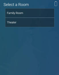
After selecting the Room, it looks like this. Note that the list is scrollable.


Some suggestions for improvement the layout:
For the Pico Remote, the remote itself appears in the list, along with each button. It would be nice if the buttons were in a sub-menu under the Remote. Selecting the Remote would expand the list and selecting it again would collapse it.
I tried assigning the Pico Remote to the Equipment Room, so that only the buttons would be displayed. That works, but it adds the Equipment Room to the list of rooms to choose from.
Buttons don’t have a toggle. Having both OFF and ON is confusing.
Scenes are just buttons on the Hub. They don’t need OFF and ON either.