

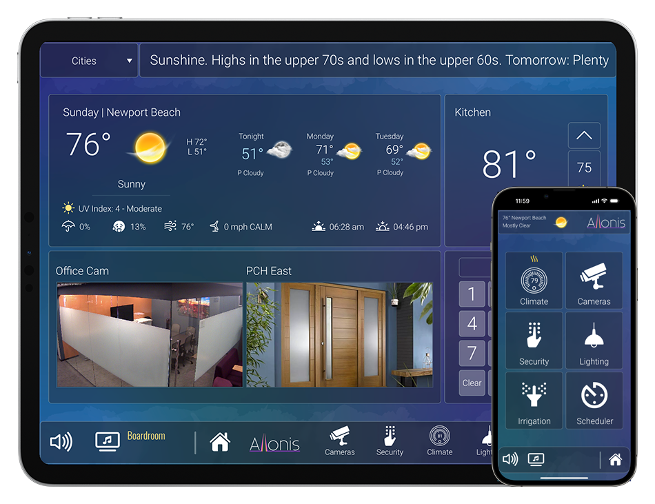

Preview any HDMI video source on your myServer 6 user interface
Let your Bar patrons listen to their choice of TV audio broadcasts
Stream your music to dozens of your boating flotillas or RV friends so you are all partying to the same vibe
Allonis's unique myCapture products connect to HDMI audio and video sources and digitally encode and multicast streams the signals via ethernet or WiFi. This enables a HDMI video signal to be displayed on a myServer browser screen. NO "App" is required to be installed so your wait staff doesn't have to be IT consultants! Additionally, one can stream the audio to a smartphone device. This is used with Allonis's myStreamer software that enables bar patrons to listen to the TV content in the privacy of their smartphone ear buds.
myCapture1 supports one HDMI input / output. This is packaged to be used with a myServer 6 control system and it's 1U rack mount.
myCapture6 has 6 HDMI inputs/ outputs. This is packaged with it's own 1U case. Includes internal router software to separate Control Network from the Guest streaming network for security purposes.
Both must be used with a myServer 6 control system (not included) and must be software configured by Allonis (quoted to the specifics of the project).
As video consumes lots of CPU and network bandwidth, Up to 1 Video signal at a time to be previewed on both devices.
Hundreds of concurrent audio connections are possible due to the multicast technology Allonis has incorporated. (one to many connections).
Connections:
myCapture1
- The HDMI source device (DirecTV, Cable Box, video streamer) connects to the HDMI Input.
- The HDMI output connects to the TV or Video Matrix Input.
- If used with a Video Matrix, the Video Matrix Output then goes to the TV.
- The myCapture1 computer is connected to the Control Network (same network as myServer 6 controller).
- The power connector in the back connects to the included USB-C power supply. This power supply should be connected to a UPS (not included)
myCapture6 and 12
In addition to the connections described for myCapture1
- The myCapture6 Left ethernet port connects to the Guest Network (looking from the back with the computer on the left side).
- The power connector in the back left connects to the included USB-C 4amp power supply. This power supplies should be connected to a UPS (not included).
- The myCapture6 internal USB hub(s) connects to the included 3.5Amp power supply(s). These power supplies should also be connected to a UPS. You should always power this connection before you power the left USB-C connection (the myServer Controller). The case fan is powered off of the first Capture USB hub.
- Internally the wiring of the USB capture hardware is critical to addressing. The Top Left (looking from the rear panel) is #1. #2 is down from that. The next column to the right is #4 and #6 is bottom right. If there are two banks, the first bank's USB hub is plugged into the TOP USB on the back of the OrangePi5Plus USB3.0 connector. The second bank (on the right) is connected to the bottom USB. The order is important.
It is critical how the usb hubs are connected to the OrangePi5Plus's rear USB ports. The Middle bank of capture boards (looking from the Modular Case rear) are wired to "Hub 1" which is connected to the TOP OrangePi5Plus connector. The Right bank Hub 2 is connected to the bottom.
If hubs or HDMI capture boards are wired differently than original, then the system will have to be painstakingly reprogrammed by Allonis.
Here are how the HDMI capture boards are wired to their respective Hubs:
| Column | Hub | Hub Position | HDMI Capture Position |
| 1 | 1 | 1 | Top Left |
| 1 | 1 | 2 | Middle Left |
| 1 | 1 | 3 | Bottom Left |
| 2 | 1 | 4 | Top Right |
| 2 | 1 | 5 | Middle Right |
| 2 | 1 | 6 | Bottom Right |
| None | 1 | 7 | Empty |
| 3 | 2 | 1 | Top Left |
| 3 | 2 | 2 | Middle Left |
| 3 | 2 | 3 | Bottom Left |
| 4 | 2 | 4 | Top Right |
| 4 | 2 | 5 | Middle Right |
| 4 | 2 | 6 | Bottom Right |
| None | 2 | 7 | USB Fan |
Software requirements (Most can ignore this section as Allonis pre-builds the system for you)
- myServer 6 with Active License
- Media Engine Driver
- Configure the Capture Card
sudo apt update
sudo apt full-upgrade
reboot
sudo nano /boot/config.txt
Under the CM4 section, enable "dtoverlay=dwc2,dr_mode=host"
reboot
sudo nano /etc/udev/rules.d/85-my-usb-audio.rules
SUBSYSTEM!="sound", GOTO="my_usb_audio_end"
ACTION!="add", GOTO="my_usb_audio_end"
DEVPATH=="/devices/platform/scb/fd500000.pcie/pci0000:00/0000:00:00.0/0000:01:00.0/usb1/1-1/1-1.4/1-1.4.1/1-1.4.1.3/1-1.4.1.3:1.2/sound/card?", ATTR{id}="Channel_1"
DEVPATH=="/devices/platform/scb/fd500000.pcie/pci0000:00/0000:00:00.0/0000:01:00.0/usb1/1-1/1-1.4/1-1.4.1/1-1.4.1.1/1-1.4.1.1:1.2/sound/card?", ATTR{id}="Channel_2"
DEVPATH=="/devices/platform/scb/fd500000.pcie/pci0000:00/0000:00:00.0/0000:01:00.0/usb1/1-1/1-1.4/1-1.4.1/1-1.4.1.2/1-1.4.1.2:1.2/sound/card?", ATTR{id}="Channel_3"
DEVPATH=="/devices/platform/scb/fd500000.pcie/pci0000:00/0000:00:00.0/0000:01:00.0/usb1/1-1/1-1.4/1-1.4.4/1-1.4.4:1.2/sound/card?", ATTR{id}="Channel_4"
DEVPATH=="/devices/platform/scb/fd500000.pcie/pci0000:00/0000:00:00.0/0000:01:00.0/usb1/1-1/1-1.4/1-1.4.3/1-1.4.3:1.2/sound/card?", ATTR{id}="Channel_5"
DEVPATH=="/devices/platform/scb/fd500000.pcie/pci0000:00/0000:00:00.0/0000:01:00.0/usb1/1-1/1-1.4/1-1.4.2/1-1.4.2:1.2/sound/card?", ATTR{id}="Channel_6"
LABEL="my_usb_audio_end"
arecord -l
MediaEngine|AddOvenMediaEngine~Host~127.0.0.1
MediaEngine|AddSource~Channel #1~Audio192~Channel_1~1
Search for init.captures in Macros
init.captures:
Macro|
// for production change 127.0.0.1 to actual IP address!
MediaEngine|AddOvenMediaEngine~Host~127.0.0.1!
MediaEngine|AddSource~Channel #1~Audio192~Channel_1~1!
MediaEngine|AddSource~Channel #2~Audio192~Channel_2~2!
MediaEngine|AddSource~Channel #3~Audio192~Channel_3~3!
MediaEngine|AddSource~Channel #4~Audio192~Channel_4~4!
MediaEngine|AddSource~Channel #5~Audio192~Channel_5~5!
MediaEngine|AddSource~Channel #6~Audio192~Channel_6~6!
// fini
Run init.captures macro to populate media engine devices