


Adding VLAN Support to Allonis L3 POE Switches
This document addresses the configuration of VLANs on generic L3 POE switches so that they can properly support a Control, A/V over IP and AES67 virtual network. As media digital data consumes much bandwidth, it is important for these devices to be on their own VLANs. myServer does need to be a member of these VLANs so it can control those devices.
It is very difficult to get a network setup properly for all digital Media devices to work properly. Allonis highly recommends to purchase Allonis's network switches that have been tested to work, and just as importantly, that Allonis has experience in configuring for your project.
myServer and other devices on the Control network also needs access to Internet (for content and remote administration).
The off the shelf L3 switch requires the following additional modifications to fully support a working VLAN environment. While this document uses a 48 port switch these instructions are valid for any size switch. Note that firmware and configuration backups must be for same size switch and not across different port switches.
Defaults
Port 48 is connected to the "house" / "bar" network that has access to the Internet.
IP: 192.168.1.200
admin / admin user ID / password
Note: If Allonis is configuring the media / control network, we will upload the custom configuration file that auto sets up most of the switch. We will modify the IP address of the switch to the network. We will custom configure the port settings for the hardware of the project.
Prerequisites – Documenting the port layout
For our example we will use the following switch port layouts. Note that no two systems have same number or type of devices, so this is just an example.
Ports 1-12 will be for AVOIP traffic (Encoders). They can be configured to feed A/V over IP traffic to downstream switches. VLAN 20 Video sources connect to these.
Ports 13-38 will be for AVOIP traffic (Decoders). They can be configured to feed A/V over IP traffic to downstream switches. VLAN 20 These are typically mounted at the back of the TV and connected via short HDMI cable to TV.
Ports 1-38 can really be used by either Decoders or Encoders.
Ports 39-40 will be used for Control Devices ethernet switch (that can be on less expensive L1 (dumb) network switch). VLAN 10
Ports 41-42 will be used for AES67 Audio over IP traffic. VLAN 30
Port 43-45 will be used for diagnostics (typically a laptop). This has access to all VLANs and Internet. VLAN 10, VLAN 20, VLAN 30, VLAN 40. We highly recommend this laptop is available for system configuration. Windows OS, TeamViewer Host software installed. We will need the TeamViewer ID / password for access. We also recommend this laptop is on a Wifi Internet connection as well.
Port 46 - 47 is for the myServer controller ethernet connection(s). this has access to all VLANs and Internet. Two for redundancy myServer controllers. VLAN 10, VLAN 20, VLAN 30, VLAN 40
Port 48 is used for connection to the "house" / "Bar" network (that is typically where Internet is accessible)
Ports T1- T4 will be generic trunk fiber ports for connection to upstream (primary) / downstream (secondary)network switches. VLAN 10, VLAN 20, VLAN 30, VLAN 40 Connector:
1.25G 850nm Multimode SFP LC Transceiver Fiber Module 550 Meters 1000Base-SX LC MMF
VLAN definitions
We will define three VLANS that are each assigned unique roles on the network.
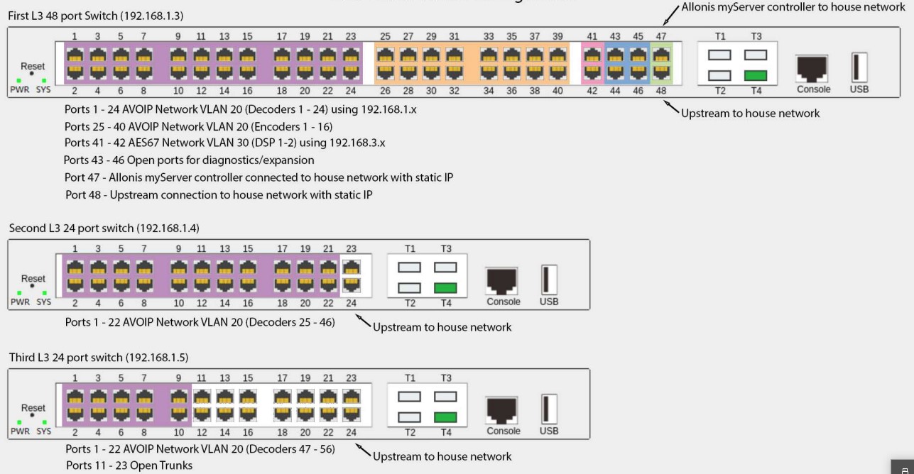
You will note that we use the Fiber connections to cascade from the Primary switch to Switches 2 and 3. Fiber is used for the excellent long distance and network bandwidth capacity. The Secondary switches can be in a different building from the primary, interconnected by a long fiber connection. We use Gigabit Fiber SFP (LC) Multi-Mode Optical Transceiver Modules connected with LC fiber (two per connection).
Use T1 on Switch 1 to connect to Switch 2's T1 port and T2 for Switch 3 T1 port.
Standard Small system support for Control, VideoOverIP and AES67 audio:
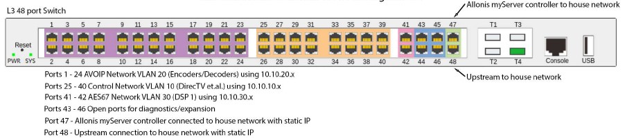
This document will make the following assumptions. Modify as necessary for your active installation. Recommended is to follow the assumptions for simplicity.
VLAN10 (Control Network = with Internet)
VLAN ID = 10, IP Address = 10.10.10.251/24, DHCP Range 10.10.10.5 – 10.10.10.248/24
VLAN20 (AVOIP)
VLAN ID = 20, IP Address = 10.10.20.251/24, DHCP Range 10.10.20.5 – 10.10.20.250/24. Note: 925 Video over IP do not support DHCP so the DHCP server is typically shut off for these ports.
VLAN30 (AES67)
VLAN ID = 30, IP Address = 10.10.30.251/24, DHCP Range 10.10.30.5 – 10.10.30.250/24
VLAN40 (TV Control - no Internet). Note: No Internet keeps TVs from getting inadvertant firmware updates that might break TV control functions. If "Smart TVs" are use that require Internet for content, put those on VLAN 10.
VLAN ID = 40, IP Address = 10.10.40.251/24, DHCP Range 10.10.40.5 – 10.10.40.250/24
If Allonis is managing the media / control network, Allonis will need to know which ports each type of device is connected to. Allonis will then manage the static or reserved DHCP IP addresses via the network switch and devices. The spreadsheet does not need to have these addresses filled out by Integrator / customer.
Step-by-Step Guide (Note: Allonis typically does the below for projects that Allonis is managing the media / control network - highly recommended).
- Get the switch on the network.
The L3 switches will always default to an IP address that varies by manufacturer. The Allonis switches will use the IP address of 192.168.1.200. You will be presented with the main status page. Note the below pictures display a 16 port switch. Setup is similar for 48 port.
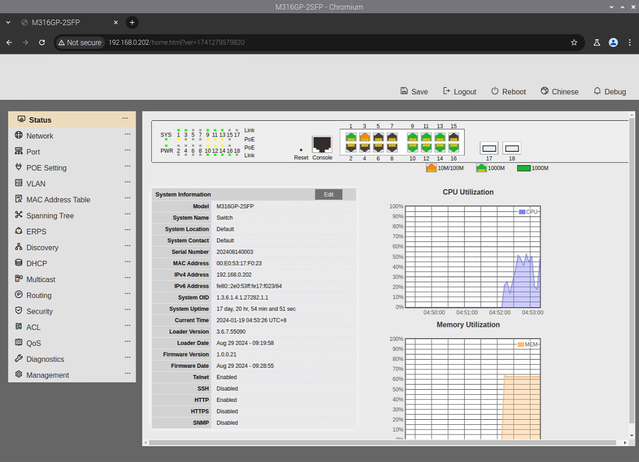
Immediately navigate to the Routing / IPV4 Interface section.
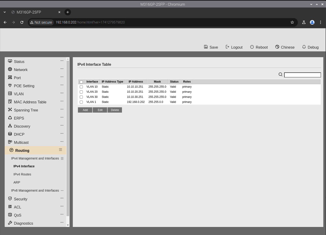
Select VLAN 1 by activating the checkbox and click on edit. Change the IP address and Network Mask to an unused IP address on the house network. In this example we us 192.168.0.202 with a network mask of 255.255.0.0. This is the IP address to manage the switches settings.
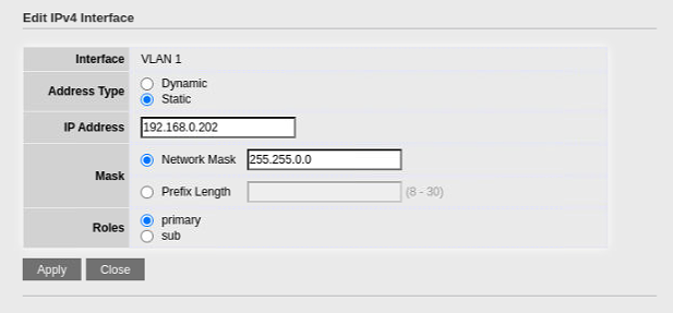
Apply the changes and then immediately change your browser to open this new address.
2. Set the time on the switch.
While not absolutely necessary setting the time on the switch can help down the road if you need to look at log files.
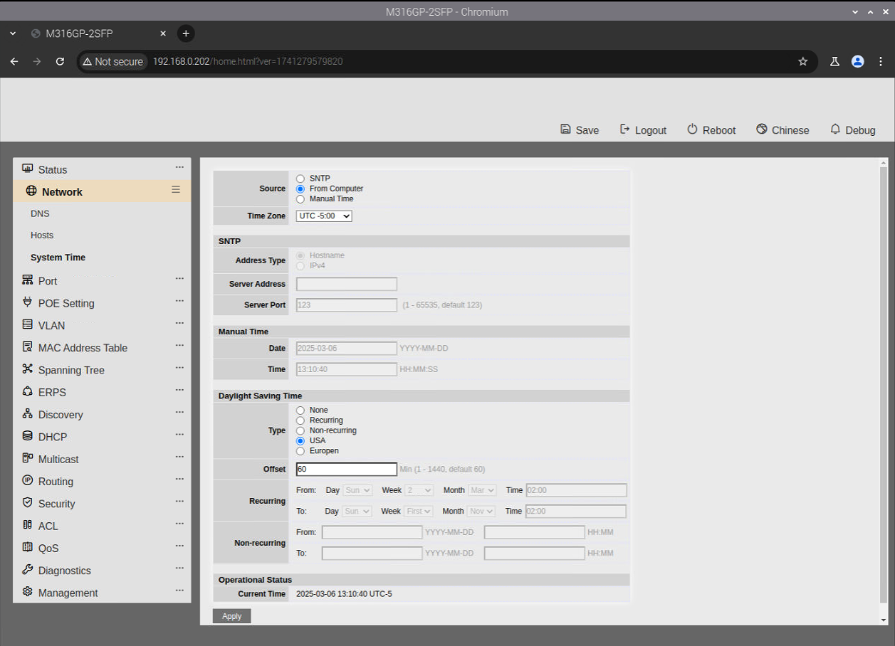
Open the Network / System Time section.
Set the Time Source to “From Computer”.
Specify the correct UTC offset for your Time Zone.
Activate Daylight Savings Time if your location uses it and set the correct type.
Then click Apply.
3. Create the VLANS
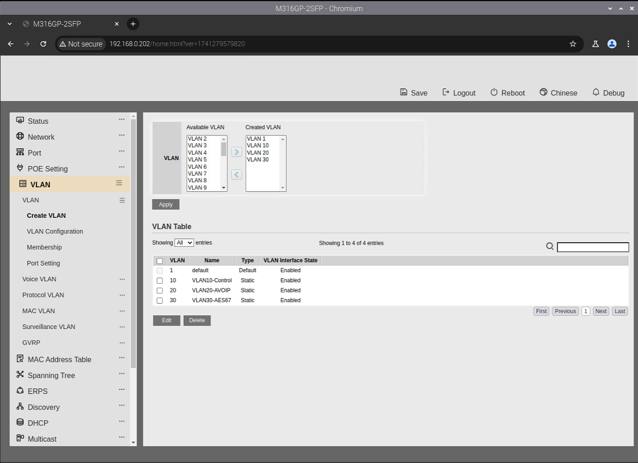
Browse to the VLAN / Create VLAN Section
Create three new VLANS as shown below.
4. Assign VLAN Port Settings.
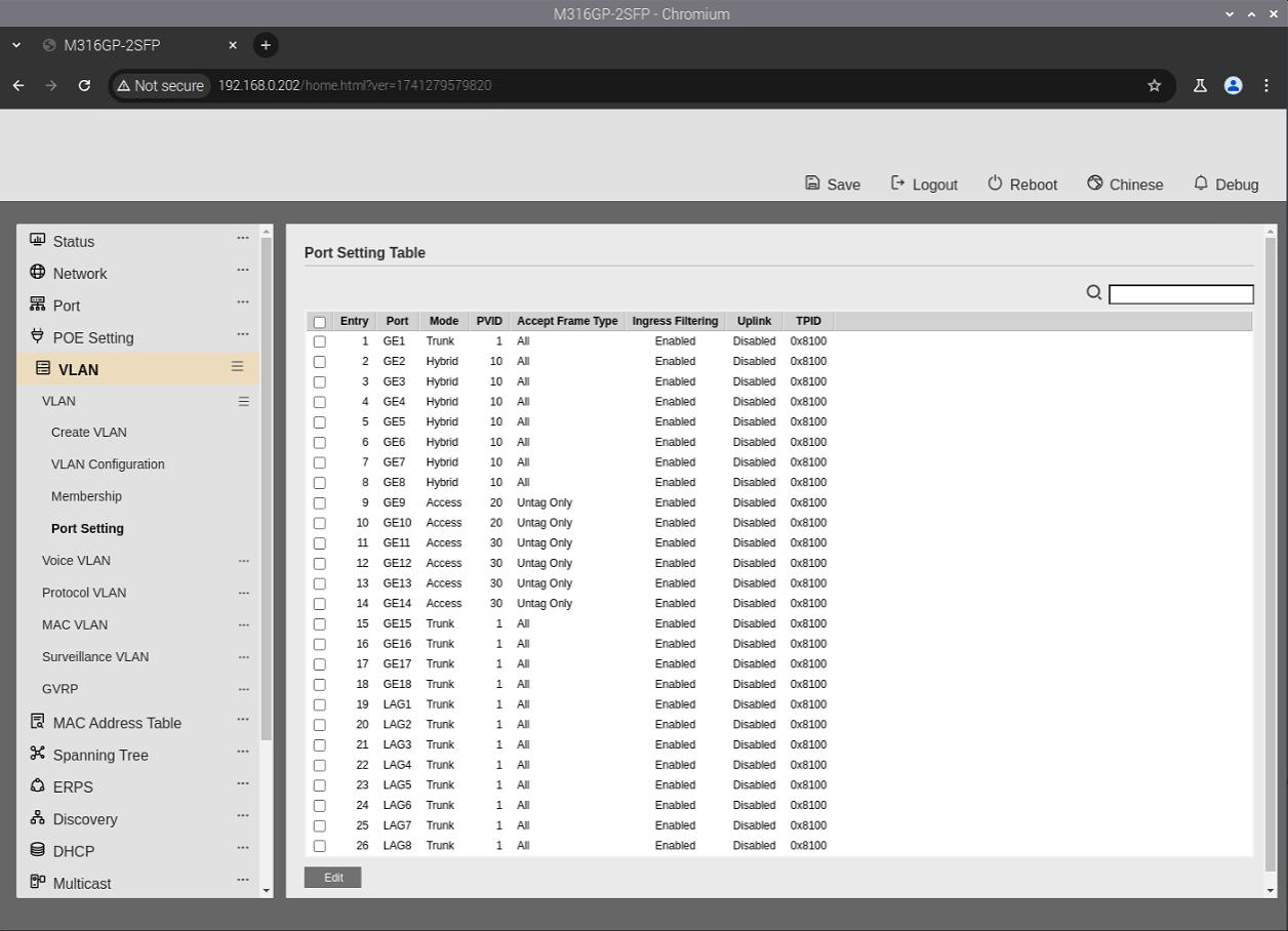
Navigate to the VLAN / Port Settings and define the mode for each of the ports on the switch.
Set port 1 to Trunk for myServer
Set ports 2-8 as Hybrid ports so that they can talk on the control network as well as have Internet access.
Set ports 9-14 as Access ports as they only have to communicate on their defined VLAN.
Ports 15-16 will remain as Truck port for connection to the house network.
It will look like this.
5. Assign VLAN Memberships
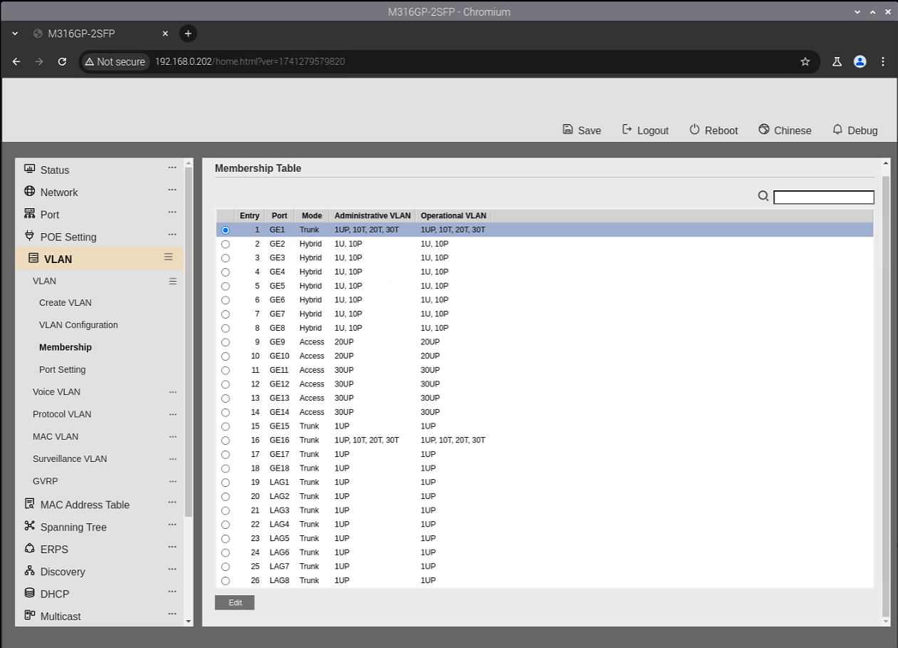
Next navigate to the VLAN / Membership section. Here we will define the VLAN associations for each port.
Port 1 is on the Control network and it is also the port were the myServer controller is plugged into. This is a special port as it has to be a member of all VLANs as well as the house network. We keep the port defined as a Trunk port and allow it to see Tagged VLAN traffic on all VLANs.
Ports 2-8 are defined as Hybrid ports on the control network. They will set VLAN 10 traffic as well as have access to the Internet.
Ports 9-10 are assigned to the AVOIP network VLAN 20. They are defined as access ports since they do not need to talk to the Internet.
Ports 11-14 are assigned to the AES67 network VLAN 30. They too are defined as access ports since they do not need to talk to the Internet. (Subject to network streaming requirements).
Port 16 is our Trunk port to the outside world on the house network.
You will need to edit each of the ports and make the appropriate membership assignments. When you are done it should look something like this.
6. Define VLAN Routing
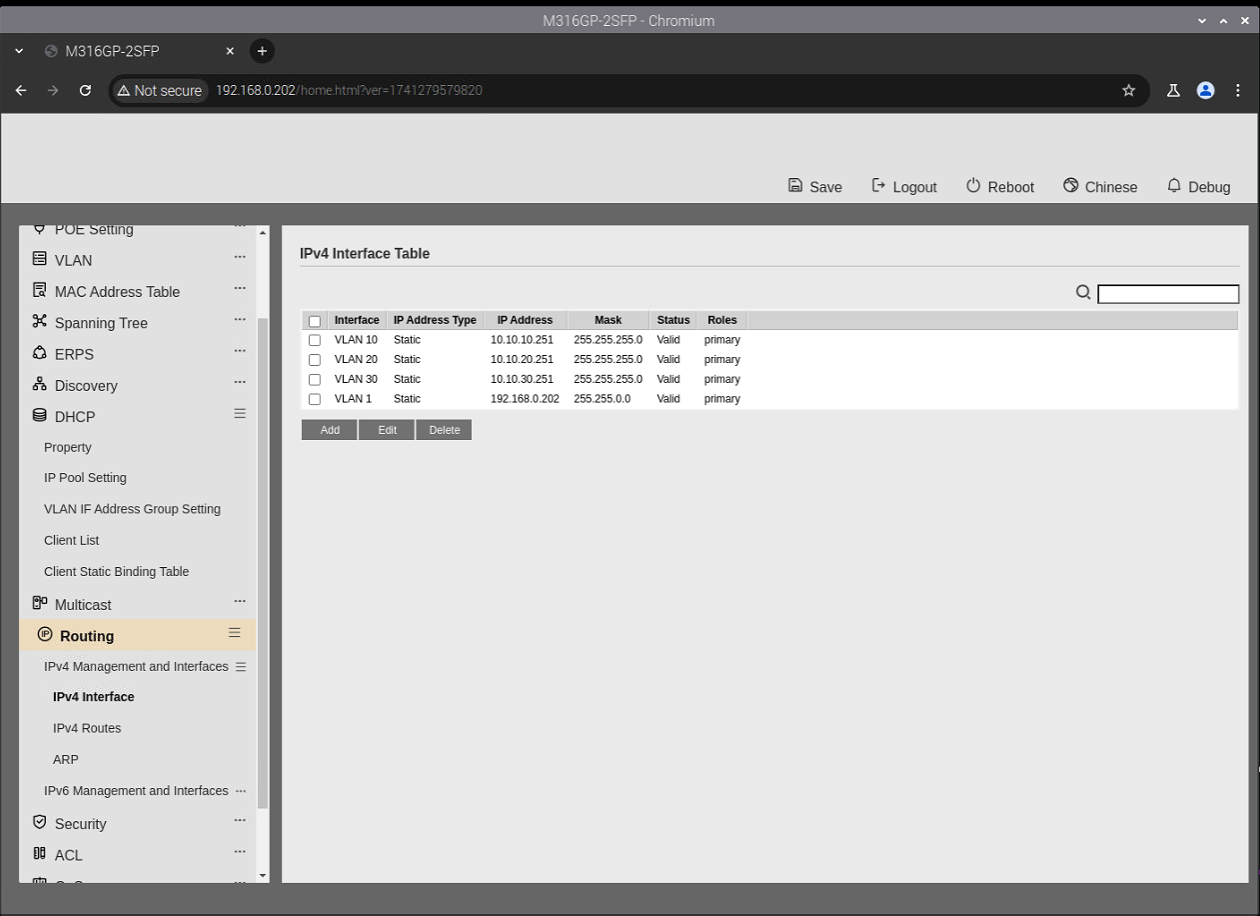
Navigate to the Routing / IPV4 Interface section.
Create a new VLAN route for each of the three VLANs.
The Network Mask typically is 255.255.255.0 or a 24 subnet mask as more addresses are hardly ever needed.
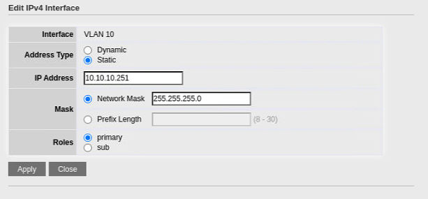
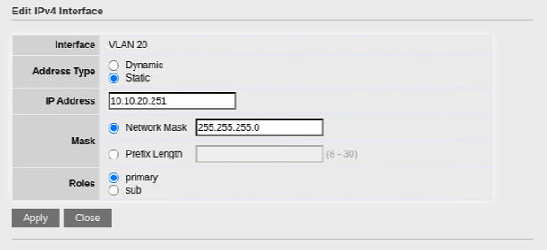
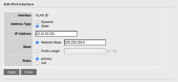
When done it should look like this.
7. Setting up VLAN DHCP
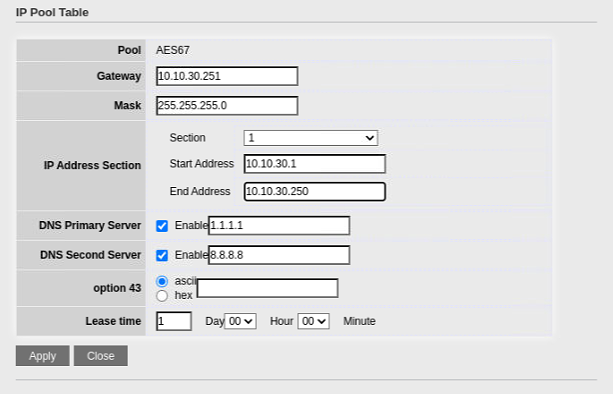
Navigate to the DHCP / IP Pool Setting Section
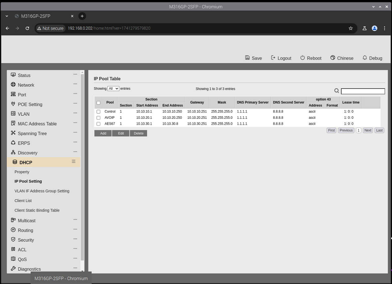
Add a new DHCP Pool for each of the VLANs.
Note: the "Control" VLAN Gateway should be 10.10.10.249 to route to the myServer 6 controller's IP (that gates the requests to the house network). The picture below is wrong. The VLAN 20 and 30 Gateway should be .251 as they don't require access to the Internet (via the house network).
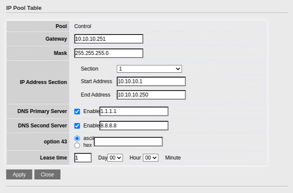
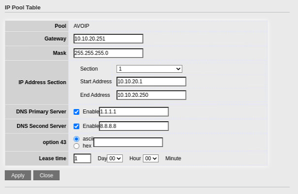
When you have defined all three VLAN pools it should look like this.
8. Binding the VLAN to the DHCP Group
Navigate to the DHCP / VLAN IF Address Group Setting section.
Add three new bindings.
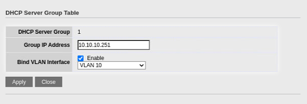
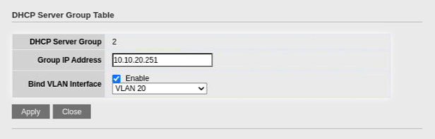
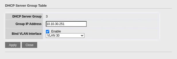
When finished it will look like.
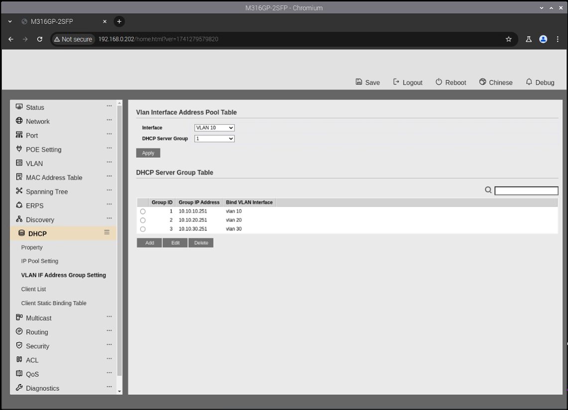
9. Enabling DHCP on the switch and ports
Next go to the DHCP Property page and enable DHCP on the switch and ports
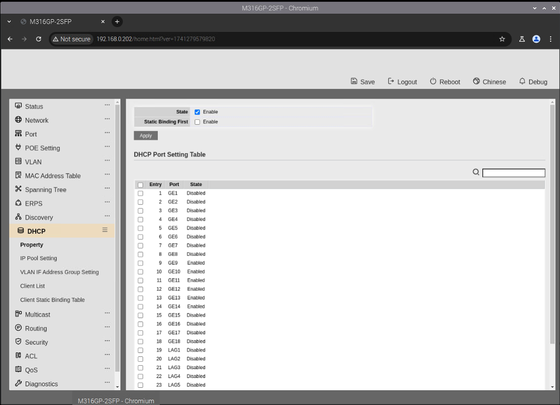
After the devices have their DHCP addresses, highly recommended to save them to the MAC tables so the addresses don't change.
10. Multicast and IGMP Snooping
Navigate to the Multicast / IGMP Snooping / Property page.
Enable IGMP Snooping on the switch and each of the VLANs.
It should look like this.
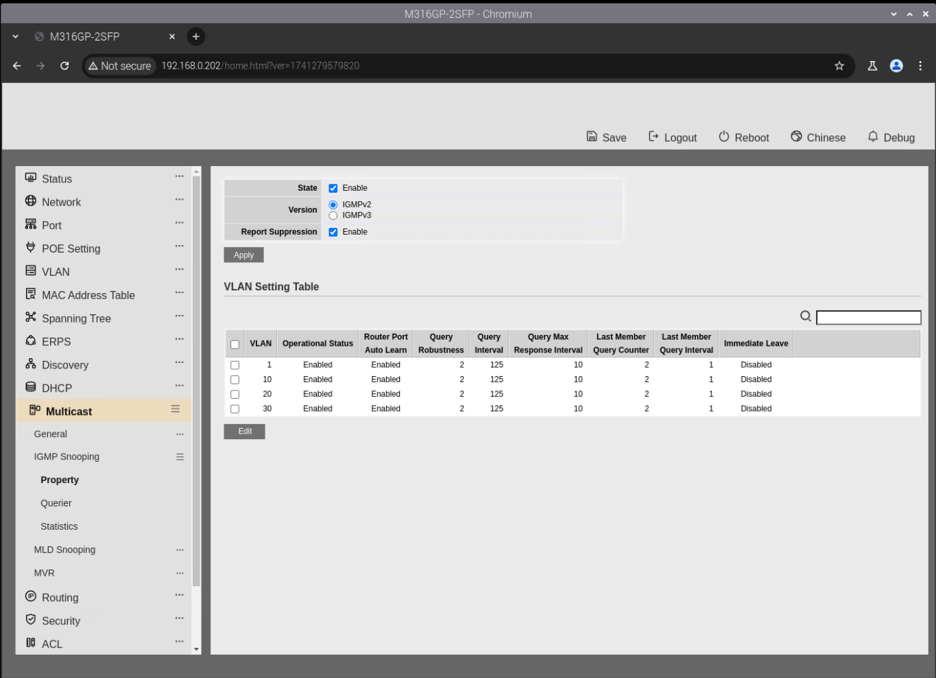
Then go to the Multicast / IGMP Snooping / Querier section. Enable the querier on the AES67 VLAN.
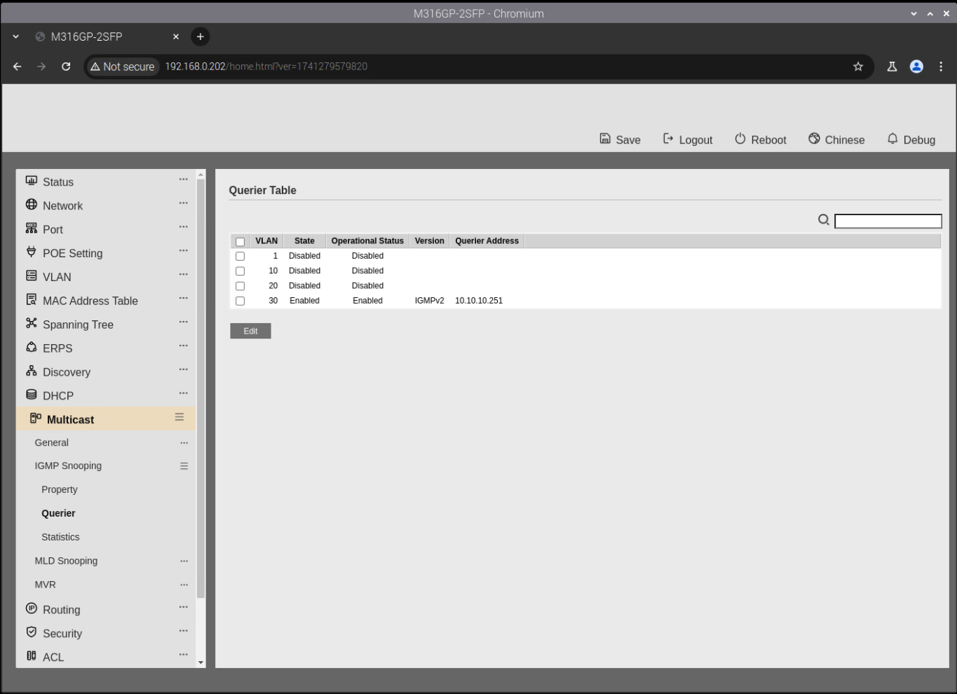
This completes the configuration of the L3 switch. Make sure to SAVE this configuration on the switch so that it be retained between switch power cycles. Recommended is to Backup the configuration so you can apply those same settings to a replacement switch (if needed).
Connect your devices and test connectivity to ensure everything is functioning properly.